
![]()
Dear Sabre Owner:
We are pleased to enclose a copy of our new Sabre Owners Manual for your boat. We have strived to make it the finest and most complete in the industry, and trust that you will find it beneficial.
There is a table of contents in the front of the manual which identifies each section with two numbers which are separated by a colon. The first number refers to the general section; the second alphabetically at the end of the manual.
Illustrations are referred to by an illustration number (e.g. I-14), and are located in the back of the manual. An Illustrations Index follows the table of contents.
Certain diagrams refer only to a particular group of boats. These illustrations are identified by the hull numbers of those boats. Also, information in the text, illustrations, and diagrams may refer to optional equipment not found on your boat.
Included in the manual are two copies of an Annual Safety Maintenance Check List. One is bound into the manual, the other is loose in order that copies can be made. It is very important that this maintenance inspection be carried out each year to assure the ongoing safety of your boat.
We have strived to provide accurate information on your boat. However, all diagrams, dimensions, and data must be considered approximate on due to variations from boat to boat, and normal construction tolerances. The actual details of your boat should be confirmed by direct inspection or measurement.
It is our sincere hope that you will find this manual useful in the operation and enjoyment of your Sabre.
Happy Sailing!
SABRE YACHTS

RH/cg
Enclosures
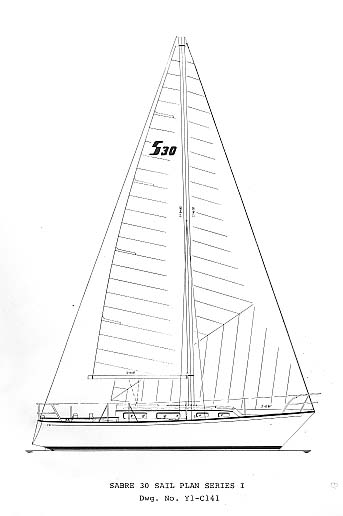
SABRE 30 SAIL PLAN SERIES I
Dwg. No. Y1-C141
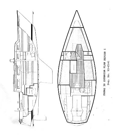
SABRE 30 INTERIOR PLAN SERIES I
Dwg. No. Y2-C141
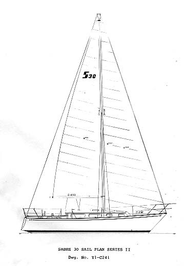
SABRE 30 SAIL PLAN SERIES II
Dwg. No. Y1-C241
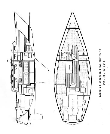
SABRE 30 INTERIOR PLAN SERIES II
Dwg. No. Y2-C241
SABRE YACHTS
OWNER'S MANUAL SECTIONS
2.00 Responsibility of your Dealer
3.00 Responsibility of the Owner
4.00 Warranties and Owners Registration
5.00 Design Concept and Specifications
7.00 Commissioning Procedures and Commissioning Check List
10.00 Safety Maintenance and Annual Safety Maintenance Check List
11.00 General Maintenance - Exterior
12.00 General Maintenance - Interior
13.00 Spars and Rigging - Tuning and Adjustment
14.00 Sails - Selection and Adjustment
16.00 Engine - Specifications and Operating Instructions
17.00 Drive Shaft and Propeller Systems
20.00 Electrical System - 12 Volt
21.00 Electrical System - 110 Volt
25.00 Drainage System and Seacocks
26.00 Head and Disposal Systems
29.00 Optional Equipment and Electronics
SABRE 30 ILLUSTRATIONS INDEX
| Title | Drawing No. | Illustration No. |
| Toe Rail, Rub Rail & Deck to Hull Joint | D1-V102 | I-01 |
| Mast Step Assembly | D3-V101 | I-02 |
| Steering: | ||
| Rudder and Tiller Assembly | S1-V101 | I-04 |
| Rudder and Wheel Assembly | S1-V102 | I-05 |
| Stanchion Post Assembly | D2-V101 | I-06 |
| Cockpit Drain Assembly | P3-V211 | I-07 |
| Genoa Track Installation | D3-V401 | I-08, I-08A, I-08B |
| Chainplate Assembly | D3-V202 | I-09 |
| Thru Hull and Seacock Installation | P3-V221 | I-10 |
| Shaft Log and Coupling Assembly | A2-V101 | I-11 |
| Keel to Hull Installation | K0-V101 | I-12 |
| Galley Sink, Ice Box Drainage System | P3-V111 | I-13 |
| Lifting Strap Locations | L1-C101 | I-14 |
| Rudder Post and Drive Wheel Assembly | S2-V101 | I-15 |
| Prop, Shaft, Strut Assembly | A2-V201 | I-16 |
| Fuel System | A4-V101 | I-17 |
| Engine Exhaust and Water Intake System | A3-V101 | I-18 |
| Heat Transfer System | A3-C101 | I-19 |
| Plumbing - Waste Water System: | ||
| Head and Holding Tank | P2-V101 | I-20 |
| With "Y" Valve and Seacock | P2-V201 | I-21 |
| With Pump Out, Valve and Seacock | P2-V301 | I-22 |
| Lectra/San Waste Treatment System | P2-V401 | I-23 |
| Ratelco Stove Pipe Installation | D0-V101 | I-24 |
| Jiffy Reefing Detail | R3-V101 | I-25, I-25A |
| Plumbing - Water Systems: | ||
| Fresh Water System | P1-C101 | I-26 |
| Fresh Water with Auxiliary Tank | P1-C102 | I-27 |
| Hot and Cold Pressurized Water | P1-C103 | I-28 |
| Pressurized Water with Auxiliary Tank | P1-C104 | I-29 |
| Hot Water Tank Diagram | P1-C001 | I-30 |
| Bilge Drainage System | P4-C101 | I-31 |
| Instrument Locations | A7-V101 | I-33 |
| Electrical Systems: | ||
| 12 Volt DC System - Diagram #1 | E2-C204 | I-34, I-34A, I-34B, I-34C |
| 12 Volt DC System - Diagram #2 | E2-C209 | I-35, I-35A, I-35B, I-35C, I-35D |
| 110 Volt AC System | E1-C101 | I-36 |
| Lightning Protection and Bonding System | E2-C207 | I-37 |
| Engine Wiring System | E3-C106 | I-38, I-38A, I-38B, I-38C, I-38D, I-38E |
| Boat Cradles: | ||
| Fin Keel - Plan and Profile | L2-C111 | I-39 |
| Fin Keel - End Views | L2-C112 | I-40 |
| Shoal Draft - Plan and Profile | L2-C121 | I-42 |
| Shoal Draft - End Views | L2-C122 | I-43 |
This owner's manual has been prepared to provide you with detailed information for the use and maintenance of your yacht in a safe and enjoyable manner. A separate loose-leaf binder is provided with individual instruction manuals and Warranty Registration cards from the suppliers of major equipment items used in the construction of your yacht.
Sailing is a most enjoyable activity, but due regard must be given to the power of the sea. Your Sabre must be handled with appropriate caution and knowledge of the hazards of sailing. It also must be maintained in accordance with the instructions provided by Sabre Yachts and its suppliers, and in accordance with American Boat and Yacht Council standards.
Sabre yachts are constructed in a modern plant specifically designed for the production of auxiliary sailing yachts. It is located in the small rural town of South Casco. This is a region of dedicated Maine craftsmen whose skills are ideally suited to the construction of fine yachts. Our Quality Engineering Department, staffed by engineers and experienced sailors, thoroughly monitors and inspects the construction of each Sabre to assure that it is built to our demanding quality standards.
It is Sabre Yachts' policy to continually improve and modify our products. Thus you may find that your Sabre has different details or equipment than shown in this manual. In each case, the new details or equipment have been carefully evaluated to determine that it is consistent with the Sabre commitment to excellence.
You Sabre is identified by a Hull Identification Number (HIN) molded into the gelcoat at the top right hand corner of the transom in accordance with U.S. Coast Guard Regulations. Please identify your model and hull number when contacting your dealer or Sabre for any reason. The first three letters of the HIN identify the builder with the code HWS, the next two numbers identify the model (e.g. 28), the next three numbers are the hull number of your yacht (e.g. 361) and the last four digits and letters signify the month and year of manufacture (e.g.: M81A reads M81 as Model year 1981, and A as August which is the first month of the model year, B=September, C=October, etc.)
It is the responsibility of your Sabre Dealer to commission your yacht in accordance with the Sabre Yachts' Commissioning Procedure, a copy of which is included in this manual. Please be sure that the Commissioning Check List is completed by your dealer and returned to Sabre, as failure to do so may invalidate your warranty.
We have strived to provide you with the most complete and detailed owner's manual in the sailboat industry. Your Sabre dealer or the Sabre Yachts' Customer Service Department would be pleased to provide you with any information you require that is not in this manual.
2:00 RESPONSIBILITY OF YOUR DEALER
All Sabre yachts are sold through Authorized Sabre Dealers who have been selected to represent the company on the basis of their knowledge of yachts and their ability to provide you with the service you deserve. The are experts in their profession who realize that they must provide you with a high level of service and attention when you purchase a Sabre.
Your Sabre Dealer is responsible to the following procedures connected with the purchase and commissioning of your yacht.
2:01 Preparing a detailed specification list for your yacht, including options, colors and upholstery selections at time of ordering.
2:02 Inspecting the yacht on delivery for loss and damage in transit, and the processing of all claims against the transport company. Should you notice any loss or damage you must notify your dealer within 30 days of arrival, as neither the carrier nor Sabre can honor claims beyond 30 days.
2:03 Inspecting the Equipment boxes that come with the yacht to assure that all items are received in accordance with the Sabre packing list.
2:04 Commissioning the yacht in accordance with the Sabre Commissioning Check List. The dealer must check and initial each item on the list, and return the list to Sabre.
2:05 Activating and checking all mechanical systems under the conditions of actual usage.
2:06 Stepping the spars and installing all rigging. Tuning and adjustment of the rigging must be carried out under actual sailing conditions. Incorrect adjustments can lead to mast failure.
2:07 Instructing you on the use of your yacht and all its systems.
2:08 Providing all necessary assistance and service under the terms of the Limited Warranty on your yacht, including the processing of all claims with Sabre Yachts.
3:00 RESPONSIBILITY OF THE OWNER
For maximum safety and enjoyment of your Sabre, due regard must be given to the hazards of sailing, and to proper maintenance procedures. The following is a partial list of items that are the Responsibility of the Owner for the safe operation of your yacht. However, this must be considered only a partial list of the safety obligations of the owner to be used as a guideline. Consult your local U.S. Coast Guard and Power Squadron offices for additional information on the safe operation of your yacht.
3:01 Complete the Warranty Registration form and return it to Sabre Yachts promptly.
3:02 Advise Sabre Yachts of any change of address, or a change of ownership, to assist us in maintaining an accurate list of owners for possible future mailings regarding safety information about your yacht.
3:03 Confirm that all items that are the Responsibility of the Dealer, outlined in Section 2:00, are completed by your dealer. If your yacht is delivered to a location other than the official address of your Sabre dealer, it becomes your sole responsibility to supervise the commissioning of your yacht, and to ensure that all items listed as the Responsibility of the Dealer are completed by competent professional marine service personnel.
3:04 Operate your yacht in accordance with instructions provided in all sections of this owner's manual, the individual supplier instruction manuals provided, and all applicable U.S. Coast Guard and other regulations.
3:05 Supervise the maintenance of your yacht by competent marine service personnel, in accordance with all instructions provided in this owner's manual, the individual supplier instruction manuals, the U.S. Coast Guard standards, the American Boat and Yacht Council standards, and all other applicable standards.
3:06 Supply and maintain all additional safety equipment on board as required or recommended by the U.S. Coast Guard and International Offshore Racing Council for your size yacht and the nature of your voyage.
3:07 Observe the requirements of the Sabre Boating Safety Check List each time you use your boat before operation. A copy of this check list is located on the underside of the cockpit locker lid giving access to the engine ignition key. Additional copies are available from Sabre Yachts upon request.
1. EXPERIENCED CREW - Are there at least two experienced persons on board who are familiar with the operation of the boat and all safety gear, each capable of acting as skipper in case of emergency? Are they familiar with the "Right-of-Way" rules?
2. WEATHER CONDITIONS - Is it safe to go out? Do you know the weather forecast?
3. FLOAT PLAN - Does anyone ashore know where you are going and when you plan to return?
4. CHARTS - Do you have up-to-date charts for the waters you will be navigating?
5. LIFE SAVING DEVICES - One for each person on board?
6. FUEL SYSTEM - Check for fuel leaks, fumes and adequate fuel. Operate the blower at least four minutes before starting engine.
7. EXHAUST SYSTEM - Check for wear or deterioration in the exhaust system that may allow hazardous fumes to escape.
8. STEERING SYSTEM - Working properly with signs of excessive wear?
9. ELECTRICAL SYSTEM - Navigation lights operating properly and batteries charged?
10. MAST AND RIGGING - In good condition and properly adjusted?
11. EMERGENCY GEAR - Check fire extinguishers, bilge pump, two anchors with line, first aid kit.
12. PROPER MAINTENANCE - Has this boat received adequate routine maintenance of all systems in accordance with all instructions provided?
13. ADEQUATE VENTILATION - Hatches should be open when the boat is under power to provide adequate ventilation below for the removal of hazardous fumes from the engine and exhaust systems.
Each Sabre yacht is covered by a Limited Warranty as detailed in the next two pages. Your yacht was carefully inspected at numerous stages of construction by our skilled Quality Engineering experts, but occasionally situations will occur that require attention under this limited warranty. Before proceeding with any warranty related work, you should carefully read the enclosed copy of your warranty and the guidelines listed below.
4:01 Complete the enclosed Warranty Registration card within 15 days of delivery of your yacht to validate your warranty.
4:02 Should warranty related work be required on your yacht, first contact your Sabre dealer. He is a knowledgeable professional who is familiar with your boat, and knows the most efficient way to complete the necessary work. Your Sabre Dealer will contact Sabre Yachts for authorization to proceed with the work, and for detailed instructions to correct the situation in the most expeditious and satisfactory manner.
4:03 If it is not reasonably possible to return your yacht to your own Sabre Dealer for warranty work, then make every effort to take your yacht to another authorized Sabre Dealer or service yard. If this is not possible, contact Sabre Yachts' Customer Service Department to request authorization to have the work performed at another location.
4:04 Authorization must be granted by Sabre Yachts before any work is carried out for this warranty to be valid. This is especially important if the work is to be carried out by a yard other than your Sabre Dealer.
4:05 Any claims for payment under this limited warranty must be fully documented, with details of all materials and labor used with quantities, hours, and rates. Sabre Yachts agrees to make full payment for work covered by this limited warranty on the basis of reasonable hours for the work actually performed and at prevailing rates in the area for materials and labor.
SABRE YACHTS LIMITED WARRANTY October 21, 1982
1. SABRE YACHTS WARRANTS all yachts and parts manufactured by it to be free of defects due to substandard materials and workmanship under normal use and service for a period of twelve (12) months after the date of sale to the original consumer purchaser, or twelve (12) months after the date of commissioning if preceding the sale date, except as limited herein.
2. TO VALIDATE THIS WARRANTY, THE ATTACHED WARRANTY REGISTRATION CARD must be fully completed and mailed to Sabre Yachts within fifteen (15) days of delivery to the original consumer purchaser. Failure to return this Warranty Registration Card may prevent the notification of defect and repair at manufacturer's expense, in accordance with the Federal Boat Safety Act of 1971. Additional Warranty Registration Cards are available at the dealer.
3. THIS WARRANTY DOES NOT APPLY TO: (a) engine, batteries, controls, instruments, pump or other equipment or accessories carrying their own individual warranties; (b) items installed by the dealer; (c) gelcoat damage such as crazing caused by stress, impact, weathering, or from improper maintenance; (d) finished or upholstery damage due to weathering, improper maintenance, or use of harsh solvents or cleaners; (e) any boat subject to misuse, misapplication, negligence, or accident; (f) alignment of the engine and adjustment of the stuffing box with are considered part of consumer maintenance; (g) cracks in finishes which might appear at hull to keel joint which are normal and do not indicate defective workmanship or material; (h) leaks at stanchions and chainplates due to day to day operation of the boat which are considered normal and part of consumer maintenance.
4. THIS WARRANTY WILL BE VOID IF: (a) the yacht or part is altered or repaired by persons unauthorized by Sabre; (b) a hydraulic backstay adjuster puts abnormal strain on the hull; (c) rigging changes are made without written authorization by Sabre Yachts; (d) a folding propeller is used (in which case the warranty will be void on the drive shaft, strut, and related items).
5. LIMITED WARRANTY IS MADE IN LIEU OF ALL OTHER REPRESENTATIONS, conditions, warranties, obligations, or liabilities on the part of the company. The total liability of the company for breach hereof shall be limited to the provisions herein and in no way shall the company be liable for consequential damages arising from a breach hereof. Sabre Yachts makes no other expressed warranties and intends no implied warranties. If any implied warranties are found to exist, such implied warranties will be subject to the time limits noted in this warranty. Some states do not allow limitations on how long an implied warranty lasts, so the above limitations may not apply to you.
6. IF A DEFECT IS DISCOVERED, the purchaser must notify a Authorized Sabre Dealer, or Sabre Yachts Customer Service Department at P.O. Box 10, South Casco, Maine, 04077.
7. INSPECTION OF THE DEFECT must be carried out by an Authorized Sabre Dealer, or an Authorized Sabre Service Agent, to determine the full extent of the defect before repair or replacement is authorized by Sabre Yachts.
8. AUTHORIZATION MUST BE GRANTED BY SABRE YACHTS before any work is carried out under this limited warranty. Work carried out prior to receipt of authorization will not be covered under this warranty.
9. SABRE YACHTS, OR ITS AUTHORIZED DEALER OR SERVICE AGENT, SHALL REPAIR OR REPLACE, at its discretion, defective components or parts within a reasonable time. Sabre Yachts' responsibility in respect to claims is limited to making the required repairs or replacements and no claim of breach of warranty shall be cause for cancellation or rescission of the contract of sale for any yacht. The Dealer or Authorized Service Yard is not an agent for Sabre Yachts except for the purpose of administering the above warranty to the extent herein provided and Sabre Yachts does not authorize the Dealer or any other person to assume liability to expense incurred in the replacement or repair of products other than those expressly authorized herein.
10. ANY CLAIM FOR REIMBURSEMENT under this warranty must be fully documented, providing full details of all materials and labor used with hours, quantities, and rates.
11. SABRE YACHTS ASSUMES NO RESPONSIBILITY for loss of use of the yacht, loss of time, inconvenience or other damage, consequential or otherwise, including, but not limited to, the cost of transporting the yacht to and from an Authorized Service Yard, travel, lodging, loss of revenue, loss or damage to personal property. Some states to not allow the exclusion of limitations of incidental or consequential damages, so these limitations may not apply to you.
12. THIS WARRANTY GIVES YOU SPECIFIC LEGAL RIGHTS, and you may also have other rights which vary from state to state.
13. THE COMPANY RESERVES THE RIGHT TO MAKE CHANGES in design, materials, or specifications of its products without obligation or liability to incorporate such changes in products of prior manufacture.
5:00 THE SABRE DESIGN CONCEPT - SABRE 30
All Sabre models are designed as high performance cruising yachts to combine the virtues of spacious cruising accommodations with race-winning potential at the club race level.
Our first model, the Sabre 28, was designed with the aid of an extensive model tank test program at the Stevens Institute. Our subsequent updates of the Sabre 28 design, and our other models, have evolved from the success of this development program plus our extensive racing and cruising experience each year in various Sabre models. Sabre has built a number of experimental boats to try out new concepts and ideas, and the best of these have been incorporated in our standard models over the years.
The hull shapes of our models have been designed with the optimum combination of low wave and friction resistance with maximum load carrying ability. Excellent stability is achieved by hull form and a high ballast ratio, rather than relying on a large crew sitting on the rail. Our efficient high-lift keel shapes are derived from NASA foil sections developed from aeronautical research. A skeg section is faired into the hull shape just forward of the NASA foil section rudder to improve the efficiency of the rudder and to reduce drag.
The sail plan and rigging of each model has been developed for the best balance between light air performance and heavy weather stability. The sail area has been selected to allow a full main and 150% genoa to be carried up to about 16 knots apparent wind within the maximum 25% angle of heel. However, this will vary with individual boats depending on the fullness of the sails.
Shoal draft versions of each model have been designed with a minimum sacrifice of performance for shoal water areas. The Sabre 28 and Sabre 30 have an optional shoal keel configuration. The Sabre 34 and Sabre 38 have an optional keel/centerboard that has been carefully engineered for efficiency and reliability.
The propeller shaft of each model has been offset slightly from the centerline as the result of our extensive testing of on-center and off-center shafts on experimental Sabres we have built. The offset location was found to have the best combination of efficiency with minimum rudder turbulence based on these tests.
All Sabre models undergo continual refinement, with a large number of changes and refinements each year to keep them in the forefront of their model category.
5:01 Since her introduction in 1979, over 90 Sabre 30's have been built. With the Sabre commitment to performance cruising, the Sabre 30 has a very modern hull, keel and rig design while retaining an attractive, traditional profile. An example of her popularity is the fact that of the 90 Sabre 30's we have built only several have ever been advertised for resale.
The Sabre 30 is often mistaken for a much larger yacht because of the many large yacht details evident in her deck layout and rigging. Her owners enjoy a pride of ownership rarely found in other 30 footers.
Her cruising accommodations are exceptional. She has 61 separate drawers, lockers and shelves, a comfortable galley and a convenient fold away chart table over the quarterberth. The Sabre dedication to simple, but effective designs which maximize available space is illustrated by the large main cabin table which folds neatly away on the main cabin bulkhead. The Sabre 30 features a fully enclosed head with shower sump for her pressure water/shower option.
Under sail, the Sabre 30 has the steady feel of a much larger yacht. Her modern, easily driven hull shape insures easy powering and comfortable sailing even when shorthanded.
SABRE 30 SERIES I
| LOA | 29' 11" | |
| LWL | 24' 0" | |
| Beam Maximum | 10' 0" | |
| Beam Waterline | 8' 4" | |
| Draft Standard Keel | 5' 0" | |
| Draft Shoal Keel | 4' 0" | |
| Displacement Standard Keel | 8600 lbs | |
| Displacement Shoal Keel | 8800 lbs | |
| Ballast Standard Keel | 3400 lbs | |
| Ballast Shoal Keel | 3600 lbs | |
| Sail Area Main plus 100% Fore Triangle | 432 sq. ft. | |
| Cockpit Length | 7' 2" | |
| Headroom | 6' 1" | |
| Displacement/LWL Ratio | 278%, 284% Shoal Draft | |
| Sail Area to Displacement Ratio | 16.47%, 16.23% Shoal Draft | |
| Ballast to Displacement Ratio | 40%, 41% Shoal Draft | |
| *Mast Height Above Water | 45' 0" | |
| Approximate Height on Standard Cradle | 11' 3", 10' 3" Shoal Draft | |
| Fresh Water Capacity | 22 gal. | |
| Fuel Capacity | 20 gal. | |
| Holding Tank Capacity | 24 gal. | |
| Theoretical Hull Speed | 6.6 knots | |
| *This figure does not allow for optional masthead lighting, radio antennas or masthead electronics. Bridge clearance will also vary with sea conditions and trim of boat. | ||
SABRE 30 SERIES II
| LOA | 29' 11" | |
| LWL | 24' 0" | |
| Beam Maximum | 10' 0" | |
| Beam Waterline | 8' 4" | |
| Draft Standard Keel | 5' 0" | |
| Draft Shoal Keel | 4' 0" | |
| Displacement Standard Keel | 8600 lbs | |
| Displacement Shoal Keel | 8800 lbs | |
| Ballast Standard Keel | 3600 lbs | |
| Ballast Shoal Keel | 3800 lbs | |
| Sail Area Main plus 100% Fore Triangle | 454 sq. ft. | |
| Cockpit Length | 7' 2" | |
| Headroom | 6' 1" | |
| Displacement/LWL Ratio | 278%, 284% Shoal Draft | |
| Sail Area to Displacement Ratio | 17.30, 17.04 Shoal Draft | |
| Ballast to Displacement Ratio | 40%, 41% Shoal Draft | |
| *Mast Height Above Water | 46' 6" | |
| Approximate Height on Standard Cradle | 11' 3", 10' 3" Shoal Draft | |
| Fresh Water Capacity | 22 gal. | |
| Fuel Capacity | 20 gal. | |
| Holding Tank Capacity | 30 gal. | |
| Theoretical Hull Speed | 6.6 knots | |
| *This figure does not allow for optional masthead lighting, radio antennas or masthead electronics. Bridge clearance will also vary with sea conditions and trim of boat. | ||
6:00 CONSTRUCTION DETAILS - SABRE 30
Sabre Yachts strives to employ the finest materials and construction details in building each Sabre 30 and has an ongoing policy of quality improvement under the direction of our Quality Engineering Department to keep our yachts at the forefront of marine technology. The following is a brief description of the basic construction details of your Sabre 30.
Refer to the index of sections for specific information on a subject.
6:01 HULL - The hull is a single unit fiberglass molding, which is hand laminated using the finest marine grade polyester resin. All fiberglass materials are pre-cut using templates to maintain design thickness throughout the hull. Isothalic gelcoat, approximately 15 mm. thick is first sprayed onto the highly polished hull mold, then one layer of 1.0 ounce fiberglass mat is placed throughout the hull to provide a strong and even backup for the gelcoat finish. The structural laminate schedule begins with one layer of 1.5 ounce mat and is followed by alternating layers of 1.5 ounce mat and 24 ounce roving in the following manner: 8 layers from keelson to the turn of the bilge, 6 layers from the turn of the bilge to just above the waterline and 4 layers from just above the waterline to the sheer. Balsa core panels, 1/4 " thick are also used to strengthen the flat sections of the topsides in the forward sections of the hull.
Additional reinforcing is provided in all key stress areas by overlapping extra layers of fiberglass. For example, there are 14 layers at the stem, 18 layers at the keelson and 18 layers where the keel is attached to the hull.
6:02 DECK - The Sabre 30 Deck is a single unit, hand laminated, fiberglass molding with non-skid surfaces molded in. One layer of 1.0 ounce fiberglass mat is initially placed throughout the deck to provide a strong and even back-up for the gelcoat finish. This is followed with one layer of of 10 ounce fiberglass cloth and one layer of 1.0 ounce mat. End grain balsa coring, 3/8" thick, is then applied on all walking surfaces of the deck. Additional reinforcing is provided in key stress areas such as the mast step, rudder post and stanchion bases, using appropriate thicknesses of marine plywood. The deck laminate is then finished with one layer of 1.5 ounce mat and one layer of 10 ounce cloth.
6:03 LINER - The liner has a textured pattern molded into the orthothalic gelcoat layer, reinforced with 2 ounce mat for structural strength. The liner is heavily reinforced with additional layers of mat, cloth and woven roving in areas of stress such as the mast support beam and bulkhead mounting ribs.
The deck and liner are bonded together using fiberglass putty filled with microballoons. This fiberglass putty provides structural continuity at all areas of stress, while allowing a space of approximately 1/2" between the deck and liner to thermal insulation and for recessing desk hardware bolts.
6:04 DECK TO HULL JOINT - The deck to hull joint consists of a fiberglass flange molded onto the hull, which allows stainless steel bolts with washers and aircraft locknuts to fasten the teak toerail, vinyl rub rail extrusions, deck flange and hull into one integral unit. To assure a watertight fit, five layers of butyl tape are placed on the hull flange before fastening the deck and vinyl extrusion in place with bedding compound. In addition, each stainless steel bolt is individually caulked as it is installed. When the bolts are tightened, the butyl bedding compound is compressed to fill all voids. A leak at this deck to hull joint can usually be overcome by additional tightening of the stainless steel locknuts to further compress the butyl compound. (Refer to I-01)
6:05 BULKHEADS - All bulkheads and other major interior components are fastened to the hull with fiberglass bonding tapes for structural strength. The bulkheads are also fastened to the heavily reinforced fiberglass ribs in the headliner with stainless steel screws. All voids between the bulkhead and ribs are filled with fiberglass putty before the decorative teak trim is installed.
6:06 KEEL - The one piece lead keel is cast in a metal mold to close tolerances. Stainless steel bolts are cast into the lead to attach the keel to the bottom of the hull. These bolts extend through the heavily reinforced fiberglass keel fillet molded into the hull, and are secured by stainless steel nuts and washers. The joint between the keel and the hull is filled with fiberglass putty to assure a precise fit and the bolts are bedded in compound. (Refer to section 28:00 for complete details)
6:07 RUDDER - The rudder shaft is constructed of a stainless steel pipe to which a stainless steel framework is welded. This framework is structurally bonded to one half of the fiberglass rudder shell. The other half of the fiberglass rudder shell is then bonded in place to obtain the optimum hydrofoil section for maximum steering control.
After assembly, the rudder molding and shaft are filled with a high density, closed cell urethane foam to maintain watertight integrity and designed rudder weight. A hairline crack at the joint between the two rudder halves has no structural significance. It can readily be repaired by digging out all loose material and filling with fiberglass putty. A layer of fiberglass cloth should then be applied over the affected area and sanded and faired into the rudder shape.
6:08 MAST STEP - The mast step of the Sabre 30 is located on the cabin top, with a structural system to transfer this loading to the heavily reinforced hull sections at the keel. The deck is reinforced with a plywood core and additional layers of fiberglass at this location. The structural beam in the headliner transfers the mast loading to the teak support post and the main bulkhead. The teak support post is support by a heavy floor timber fiberglassed to the hull. (Section 13:00 refers to the mast step in use, also refer to I-02)
The proper commissioning of your Sabre is the responsibility of your dealer. This is a very important step in assuring the satisfactory operation of your yacht. The construction and inspection of each Sabre is completed to the fullest extent possible at the factory. However, further commissioning and inspection is necessary under actual sailing conditions and usage. Also, this commissioning procedure should be followed in subsequent years at commissioning time.
7:01 COMMISSIONING CHECK LIST: The attached Commissioning Check List procedure should be followed by your dealer in commissioning your yacht. Each item on this list should be checked off by the dealer as the work is completed. Both the dealer and the owner should sign the bottom of the check list to confirm that all items are completed. This signed copy must be returned to Sabre Yachts as part of the warranty registration.
7:02 PROPER LIFTING: The careful placement of the lifting straps used to lift your Sabre is very important to avoid damaging the propeller shaft, and to assure that the center of gravity of the yacht is midway between the straps. Additional caution should be exercised to avoid placing a strap in contact with a speedometer or depth finder thru hull fitting. (Refer to I-14)
7:03 TRIM: Your yacht is designed to float level with the boot stripe molded into the hull under normal conditions. You may find that the trim of your yacht is affected by the weight of optional equipment and tankage, the fullness of water and fuel tanks, and by the placement of your equipment and supplies. In most cases, correct trim can be maintained by storing heavy items in appropriate locations. If needed to further adjust the trim of your yacht, 60 lb. lead trimming ballast blocks may be purchased from Sabre Yachts, together with installation instructions.
7:04 STANDING RIGGING: The careful adjustment of the standing rigging of the mast under actual sailing conditions is critical to avoid mast failure. The rigging should be adjusted to maintain a maximum bend of 3" in the lateral direction, and 6" in a fore-and-aft direction under all sailing conditions. The wire rigging will tend to permanently stretch over a period of time, as the strands bed into one another, so repeated checking of rigging adjustment is necessary. Detailed instructions for tuning the rigging are included in Section 13:00 of this manual.
7:05 BOTTOM PAINT: Antifouling bottom paint must be carefully matched to the type of paint already on the boat to avoid the blistering and peeling common to mismatched paints. (Refer to Section 11:02 for more information on bottom paints)
SABRE YACHTS
DEALER COMMISSIONING CHECK LIST MARCH 17, 1982
Dealer _________________________________________________________________
Boat Model ___________________________ Serial No. ______________________
Engine Model _________________________ Engine Serial No. _______________
Date of Commissioning ________________ Date of Delivery ________________
The following check list should be followed as a part of the minimum dealer commissioning procedure for a Sabre yacht. All work should be carried out in accordance with American Boat and Yacht Council Standards, U.S. Coast Guard, the Sabre Owner's Manual, and additional manuals provided for engine and other equipment. Failure to carry out this procedure may invalidate manufacturer's warranty.
1:00 BEFORE LAUNCHING
1:01 ___ Repaint bottom at cradle pads and at bottom of keel while boat is suspended in slings.
1:02 ___ Install knotmeter sender unit (option).
1:03 ___ Check propeller, propeller shaft nuts, cotter pin, strut and cutlass bearing.
1:04 ___ Check action of rudder.
1:05 ___ Inventory all loose equipment and report all shortages and/or damages.
1:06 ___ Install zinc on propeller shaft (Dealer supplied).
2:00 LAUNCHING
2:01 ___ Check action of all thru-hull seacocks.
2:02 ___ Check all hose clamps on engine and engine fittings, exhaust lines and cockpit drains, heads and all thru-hull fittings.
2:03 ___ Check shaft log and stuffing box packing nut.
2:04 ___ Water test windows, hatches and deck fittings for leaks.
2:05 ___ Check lifeline stanchion and rail set screws.
2:06 ___ Check lifeline turnbuckles and end fittings and tension accordingly; secure and tape cotter pins and/or rings.
3:00 RIGGING AND TUNING OF SPARS
3:01 ___ Inspect wire rigging for kinks or defects.
3:02 ___ Install standing rigging on mast. Open all cotter pins fully.
3:03 ___ Install spreaders on mast, securely fastening upper shrouds to spreader tips with stainless steel wire or end caps. Spreader tip boots should be installed to reduce sail wear.
3:04 ___ Check operation of all mast lights, antenna wires, and accessories before stepping mast.
3:05 ___ Check operation of all halyards and lifts. Lubricate sheaves if necessary.
3:06 ___ Install masthead instruments (option).
3:07 ___ Step mast and install boom.
3:08 ___ Adjust rigging tension to assure a straight mast when boat is heeled at 25 degrees. See standing rigging adjustment in owner's manual.
3:09 ___ Secure turnbuckles, clevis pins and cotter pins and protect with tape. Turnbuckle boots are also desirable.
3:10 ___ Review all running rigging for completeness.
3:11 ___ Install mainsail reef eyes and blocks on boom to suit reefing eyes in sail.
4:00 BEFORE STARTING ENGINE
4:01 ___ Review Engine Manual
4:02 ___ Align engine to shaft with rig stepped and tensioned. Engine is disconnected prior to shipment. Coupling bolts are labeled and shipped in galley drawer. (step locker in Sabre 38)
4:03 ___ Check engine coolant drain plugs.
4:04 ___ Check action of throttle, shift and engine stop controls.
4:05 ___ Fill fuel tank to at least one half full.
4:06 ___ Check fuel tank, fuel lines and fuel filter for leaks.
4:07 ___ Check engine and transmission oil levels.
4:08 ___ Check that engine water intake seacock is open.
4:09 ___ Check levels of water in fresh water engine cooling reservoir.
4:10 ___ Run engine compartment blower for 4 minutes, check air suction and discharge of vent ducts.
4:11 ___ Check battery water levels.
4:12 ___ Check that batteries are properly secured.
4:13 ___ Check battery switch, battery charge indicator (option).
4:14 ___ Check main breaker and breaker panel light.
4:15 ___ Check navigation lights, sidelights, masthead and stern lights. Check that added equipment does not obscure the lens light arc. Review current regulations with owner.
4:16 ___ Check anchor light, foredeck flood light.
4:17 ___ Check engine instrument lights, compass light.
4:18 ___ Check all cabin lights.
4:19 ___ Check shower sump pump (option).
4:20 ___ Check electric bilge pump (option).
4:21 ___ Check 110V AC shore power (option).
4:22 ___ Check 110V AC voltmeter/polarity indicator and instruct owner on its use.
4:23 ___ Check 110V AC receptacles.
4:24 ___ Check Lectra/San operation (option).
4:25 ___ Check operation of navigational instruments (option).
5:00 STARTING ENGINE
5:01 ___ Review Engine Operation manual with boat owner.
5:02 ___ Open fuel valve.
5:03 ___ Start engine. Water temp/oil pressure alarm should activate and shut off when engine starts.
5:04 ___ Check oil pressure, ammeter charge, fuel and water temperature gauges.
5:05 ___ Check exhaust water flow.
5:06 ___ Inspect engine water cooling system for leaks.
5:07 ___ Inspect exhaust system for water and exhaust leaks.
5:08 ___ Check gear shift lever in all positions and adjust cable if needed.
5:09 ___ Check throttle action and adjust cable if needed.
5:10 ___ Adjust idle speed in accordance with Engine Manual.
5:11 ___ Adjust stuffing box after engine has been run for 10-15 minutes.
5:12 ___ Check bilge for signs of fuel leaks.
5:13 ___ Recheck entire fuel system for leaks.
6:00 FRESH WATER SYSTEMS
6:01 ___ Fill fresh water tank.
6:02 ___ Check action of galley and vanity foot pumps. Note: To avoid damage to foot pump, faucet shutoff must be open.
6:03 ___ Check water system for leaks.
6:04 ___ Check pressure water faucets and systems (option).
6:05 ___ Commission water heater and check engine drive and 110V AC heating operation (option).
7:00 HEAD SYSTEM
7:01 ___ Check action of head.
7:02 ___ Check head fill and discharge hoses for leaks.
7:03 ___ Check action of holding tank.
7:04 ___ Check operation of y-valve discharge plumbing and instruct owner on proper valve positioning (option).
7:05 ___ Activate Lectra/San unit (option) in accordance with instructions. Unit may be difficult to prime with water. See owner's manual for priming procedure.
8:00 STOVES AND OVENS
8:01 ___ Review stove or oven manual with owner.
8:02 ___ Fill alcohol tank half full.
8:03 ___ Check CNG tank and system (option).
8:04 ___ Check action of all burners.
8:05 ___ Check adjustment of burner control valves.
8:06 ___ Check hoses and control valve packing nuts for air pressure or fuel leaks.
9:00 SEA TRIALS
9:01 ___ Check fit of sails.
9:02 ___ Adjust rigging to assure straight mast and proper tension on stays at maximum design angle of heel.
9:03 ___ Check electronic instruments and calibrate in accordance with instructions (option).
9:04 ___ Compensate compass.
10:00 FINAL
10:01 ___ Check fit of all drawers, doors and latches after rigging is tensioned and adjust if necessary. The stress of rigging tension usually requires that door latches be reset.
10:02 ___ Water test chainplates and re-bed if necessary.
10:03 ___ Check adjustment of steering cables after sea trials and make sure wire clamps and cable adjustment nuts are tight (option).
10:04 ___ Check fit of emergency tiller and instruct owner in its use (with wheel option).
10:05 ___ Clean boat throughout, both interior and exterior.
10:06 ___ Review Owners Manual and accessory instructions with owner.
10:07 ___ Fill out Warranty Card.
I hereby certify that the Dealer Commissioning Check List has been satisfactorily completed. Please sign and return to Sabre Yachts with Warranty Registration information.
Dealer Signature __________________________________ Date ________________
Boat Owner's Signature ____________________________ Date ________________
It has been in relatively recent years that most advancements concerning ground tackle have been made. The subject has been studies as a science and now a variety of systems have been designed to suit the numerous conditions encountered.
The booklet "Anchors and Anchoring" by R. D. Ogg, has been included in the binder of manufacturer's information. This is a most complete booklet for choosing the mooring and anchoring system best suited for your boat and conditions.
It contains information on rode size and length, anchor chains, choosing appropriate working and storm anchors, as well as a short history of the progression and development of modern anchors.
in general a minimum of two anchors should be carried at all times and enough anchor rope and chain necessary for the depth of water to be navigated during storm conditions.
Certain anchors are useful for a variety of bottom conditions. Study the charts of the area to be navigated for information concerning bottom conditions and water depth.
Permanent moorings must be marked with information on your personal identification. Also marking the buoy in such a way that is can easily be identified will benefit you in locating it in stormy or congested conditions.
The greatest hazard with a sound permanent mooring is the chafe which can occur to the rode pennant at the bow chocks. This is the single most common site of failure. Care is advised in the selection and protection of the rode pennant with appropriate chafing gear. Continual inspection of moored boats on a regular basis is necessary to insure the boat's safety.
Good safety equipment should be a priority of every sailor for the protection and comfort of his passengers. Passengers aboard should be made familiar with the safety equipment and operation of the boat in the event of an emergency. U.S. Coast Guard Regulations require that certain equipment be on board. Contact the U.S. Coast Guard for literature on the current laws.
9:01 DISTRESS SIGNALS: Visual distress signals are required by the U.S. Coast Guard for any boat 16 feet or more in length, and by all boats during night operation. A variety of devices are acceptable to meet the requirements. Check with the U.S. Coast Guard for the particular regulations and equipment. This equipment has been thoroughly tested and is easy to use.
9:02 FLOTATION DEVICES: An approved life preserver for each passenger aboard is required by the U.S. Coast Guard. There are a variety of approved styles available, choose one that you are comfortable with.
Additionally, a safety harness should be available and worn during night time sailing as well as during periods of foul weather.
9:03 FIRE EXTINGUISHERS: Approved type B:C1 fire extinguishers are installed on each yacht. They are dry chemical type with sodium bicarbonate as the basic extinguishing agent. You should become familiar with their locations and proper use. A gauge on each extinguisher readily indicates if it is in good working order.
9:04 EMERGENCY TILLER: On boats with wheel steering, a tee shaped pipe, the emergency tiller, is supplied for use in the event of steering failure. It can be easily lifted from its mounting brackets on the shelf in the cockpit locker. An emergency tiller cover plate is then removed from the cockpit floor to gain access to the rudder post and the tiller inserted for steering. (Refer to I-04)
9:05 ADDITIONAL EQUIPMENT: Other equipment that should be aboard on each yacht include: a complete first aid kit, knife, paddle, charts, compass, flashlight, whistle or horn and a bell. A quality radar reflector should be put up during heavy fog to aid boats and ships in locating you. Also include a pair of good cable cutters to cut and free the rig in case of mast failure.
Upkeep of your boat's equipment is a necessary part of its usage, ensuring your safety and the maintenance of the boat's worth.
10:01 STANDING RIGGING: Standing rigging includes all parts concerned with support of the mast. All components should be examined each time before going sailing and given a more thorough examination on a monthly basis. Spreaders should be positioned at the appropriate angles and have boots or taped ends. Bent or damaged spreaders must be replaced. Turnbuckles should all contain cotter pins top and bottom to secure their position and have boots or be taped over with plastic tape to prevent snagging of clothes or sails.
Check thoroughly the point at which the wire cable enters the swayed terminal ends. A small silicone bead around this junction will prevent salt from penetrating and will easily identify any slippage of the wire out of the terminal.
A complete inspection of all rigging should be conducted monthly and cables or parts should be replaced if any rust or breaks are found.
10:02 RUNNING RIGGING: Running rigging includes all the gear used in handling and trimming sails. The main and genoa halyards are stainless steel wire spliced to rope. As the wire cable passes over sheaves at the masthead and the turning blocks at the foot of the mast, they are exposed to continual heavy loads and flexing. This constant strain will wear on wire after a period of time so the halyards should be examined on a regular monthly basis and sooner if the boat is sailed more frequently. When signs of wear or stress are found the halyard will need replacing.
The junction of the splice between the wire and rope tends to be an area of weakness. The integrity of the splice should be checked frequently.
The rope halyards are not exposed to as severe a strain as wire halyard, yet should also be examined frequently. The ends should be protected from fraying.
10:03 LIFE LINES: As with the rigging, a thorough examination of the cable and cable ends should be conducted monthly. Routine inspection should be done every time the boat is sailed. Look for loose cables, frayed wire, or rusted fasteners and replace worn parts. Turnbuckles should be fully engaged onto the threaded rod and lock nuts tightened securely. Line tension should be snug without being overly tight. Small cotter pins will insure that turnbuckles with remain tight and the whole turnbuckle assembly should be taped with plastic tape to prevent snagging and chafe.
10:04 STANCHION POST: Stanchion posts should be securely fastened to the deck as described in Section 10:14. (Refer to I-06)
10:05 FIRE EXTINGUISHERS: Each fire extinguisher should be checked monthly. A gauge on each extinguisher allows you to easily check the charge. Each passenger should be made aware of the best way to exit the cabin in the case of a fire or other emergency.
10:07 THRU HULLS: At hauling each season all seacocks and thru hulls should be completely drained, cleaned and greased as described in Section 25:00. Adjust the retaining nut and lock nut to the appropriate tightness.
Before launching and every time before the boat is sailed each seacock must be checked for tightness and to see if they are functioning properly.
Keep all but the cockpit drain seacocks closed whenever the boat is left unattended.
Cockpit drain seacocks should be worked and inspected frequently in spite of being continually left opened. They protect the boat by maintaining the hull's water tight integrity in the event of drain hose failure. (Refer to I-07)
10:08 DECK HARDWARE: Considerable strain is applied to all deck hardware during the course of the season and each fitting should therefore be tightened at launching. Most all deck hardware is bolted through the deck and either reinforcement is molded into the fiberglass deck in that area, or aluminum backup plates are used, or both. Frequently check the tightness of these nuts and bolts especially if the boat is sailed hard. Nuts are accessible by removing access panels throughout the boat, through the anchor well and cockpit lockers, as well as along the edge of the headliner flange at the sheer.
Be careful not to over tighten deck hardware which could possibly strip the threads. Keeping all deck hardware clean and waxed will prevent any corrosion from forming. (Refer to I-06, 08)
10:09 CHAINPLATES: Chainplates are thru bolted to the bulkheads with 1/2" nuts and bolts with lock washers. Check nut and bolt tightness monthly. (Refer to I-09)
10:10 WINCHES: During active sailing periods the winches should be stripped down, cleaned and lubricated at least once a year. Disassemble, clean and lubricate the internal mechanism with a light water pump grease.
10:10 WINCHES (Cont'd)
It is recommended that you wash down winches after each sail with fresh water, dry and cover. Refer to the literature in the manufacturer's binder on the winches for detailed maintenance instruction. As with other deck hardware, removable access plates allow access to nuts for the cabin top winches and the nuts for the coaming winches are accessible through the openings of the winch pockets.
10:11 BILGE: The bilge should be checked for water and drained every time you board or leave the boat. A reinforced hose leads from the pump to the bilge. A metal strainer in the bilge protects the pump from large foreign objects. It should be checked frequently. In the event that something clogs the pump, it may be disassembled and cleared.
10:12 STEERING: Tiller and wheel steering should be thoroughly examined monthly and regularly during extended voyages. (Refer to Section 15:00 for complete steering maintenance.)
10:13 WIRING: The wiring system including the lightening protection and bonding system, should be inspected seasonally or as the need arises. Check wire insulation and terminal ends for soundness. (Refer to Sections 20:00, 21:00, 22:00, 23:00 for further details.)
10:15 ANNUAL SAFETY MAINTENANCE CHECK LIST
The following list has been compiled as a guide to check critical safety related components of the boat. It is very important that this maintenance inspection of the boat be completed each year to assure the ongoing safety of your boat.
1:00 STANDING RIGGING
1:01 ___ Check turnbuckles, threads, swages, and pins for corrosion or wear.
1:02 ___ Check chainplates for hole elongation, bolts, and mount integrity.
1:03 ___ Check mast hardware including masthead, tangs, and pins for wear and corrosion.
1:04 ___ Check mast stay and shroud wire for corrosion, wear, and burrs.
1:05 ___ Tune rig.
2:00 RUNNING RIGGING
2:01 ___ Check lines for wear and splice condition.
2:02 ___ Check block attachment and condition of sheaves.
2:03 ___ Service winches, check for free operation and ratchet stop function.
2:04 ___ Check for secure fastening of all cleats.
3:00 DECK HARDWARE
3:01 ___ Check lifeline integrity, stanchion, and rail attachment to deck.
3:02 ___ Check all chocks, cleats, and other hardware for attachment and soundness.
4:00 STEERING SYSTEM
4:01 ___ Check rudder condition.
4:02 ___ Check rudder post play in bearing tube.
4:03 ___ Check stuffing box, packing, and grease cup.
4:04 ___ Check drive wheel attachment.
4:05 ___ Check integrity of cables and chain clamps.
4:06 ___ Check steering wheel shaft lubrication and wheel security.
5:00 THRU HULL AND SEACOCKS
5:01 ___ Check seacock integrity.
5:02 ___ Check seacock attachment to hull.
5:03 ___ Check for free operation and lubrication.
5:04 ___ Check hose, integrity, attachment and clamps.
6:00 ELECTRICAL
6:01 ___ Check battery charge, terminal connections, and electrolyte condition.
6:02 ___ Check breaker panel and switch condition.
6:03 ___ Check terminal for tightness and corrosion.
6:00 ELECTRICAL (CONT'D)
6:04 ___ Check running light operation.
6:05 ___ Check ground wire attachment to keel, chainplates, mast step, thru hulls, and engine.
7:00 MECHANICAL SYSTEMS
7:01 ___ Check stove fuel system, hoses, clamps, and shut offs.
7:02 ___ Check heating stove - clearance and exhaust pipes.
8:00 ENGINE AND DRIVE TRAIN SYSTEM
8:01 ___ Check engine fluid levels and systems for leaks - shut off controls.
8:02 ___ Check throttle action - start and stop controls, cable clamps, and locknut.
8:03 ___ Check shifter cable clamps and locknuts.
8:04 ___ Check exhaust system soundness, hose clamps, and waterlock canister.
8:05 ___ Check coolant system, hose clamps, intake, and filters.
8:06 ___ Check transmission shift lever action, control wirage, fluid level, and alignment.
8:07 ___ Check trueness of shaft, coupling, and prop attachment.
8:08 ___ Check shaft log tube integrity, packing, hoses, and clamps.
8:09 ___ Check strut bolt attachment, cutlass bearing, and shaft bolts.
8:10 ___ Check all engine wire connections.
9:00 KEELS
9:01 ___ Check keel bolt nuts for tightness (on cradle to 90 foot pounds).
9:02 ___ Check centerboard cable connections, hose clamps, and winch.
10:00 PLUMBING
10:01 ___ Check bilge pump function, hose clamps, and strainer.
11:00 REPAIRS
All necessary repairs should be completed before continuing to use the boat.
The following is a general guide for use in the maintenance of your yacht's exterior. Materials of the highest quality have been used in construction and with regular attention their appearance and performance should remain new.
11:01 FIBERGLASS: As a boatbuilding material, fiberglass is recognized as one of the most maintenance free. The exterior surface is gelcoat, a color impregnated resin. Care is needed for the boat to withstand the rigors of usage.
Frequency of washing will depend on need, yet several times per season should be anticipated. Wash with mild detergent and warm, fresh water, using a soft sponge or soft natural brush. Non skid areas may require a stiffer brush. Rinse entirely with fresh water. Stubborn stains and minor scratches can be removed with conservative use of a fiberglass cleaner containing a gentle abrasive, after which the area will need waxing with a quality automotive or boat wax.
The entire topsides and superstructure should be waxed at least once yearly, with a routine of waxing at launching and hauling preferred. Leaving non-skid areas unwaxed will increase the non-skid effect.
Minor gelcoat damage may be repaired through the use of a gelcoat repair kit available from Sabre Yachts. Complete instructions are included with the kit. Other gelcoat and fiberglass damage should be referred to your Sabre dealer.
Pencil line cracks may appear in the gelcoat at corners of the deck molding, especially around the cockpit and backstay chainplate. This is strictly a surface condition in the gelcoat finish and does not indicate structural weakness.
11:02 YACHT'S BOTTOM: A quality anti-fouling bottom paint is needed to protect your boat from marine growth. Factory applied paint is Petit Unipoxy Atlantic formula, suitable for most conditions.
Different geographical locations may dictate the need for a specific paint. See your Sabre dealer for this information. Painting is recommended before launching each season.
It is necessary to properly prepare the new fiberglass surface for painting by etching with sandpaper or a chemical product designed for this purpose. This is followed by washing twice with a fiberglass solvent wash. Paint should then be rolled on to produce as smooth a surface as possible. Certain bottom paints are chemically incompatible and care must be taken in their selection. Read all information and instructions supplied with paint.
At hauling and as required through the season, the bottom must be cleaned of all marine growth. If the yacht is hauled for other reasons, and is to be kept out of the water for any length of time, the bottom also needs cleaning then. This will prevent the marine growth from having the opportunity to dry and become hardened.
Scrub the bottom with a stiff scrub brush and detergent diluted in warm water. A high pressure hose, if available, is useful and a flexible stainless steel spatula used with care can be helpful.
The external crack at the keel joint may be filled at this time. Refer to Section 28:00 concerning this area. This can be followed by sanding the entire bottom to prepare for paint of to produce a smooth racing surface. (Refer also to I-10)
11:03 COVE STRIPE: The cove stripe is a high quality colored plastic tape. It may be cleaned during the regular washing with mild detergent. Abrasive or wax removing cleaners may damage the tape and/or effect it's adhesion to the hull. If damaged, the appropriate replacement tape can be purchased from Sabre Yachts.
11:04 RUB RAIL: A vinyl rub rail encloses the deck to hull joint. It is very durable and can be washed. Stubborn stains or discoloration can be removed using an abrasive cleaner being careful to avoid neighboring gelcoat surfaces.
11:05 PORTS & HATCHES: The ports and hatches are either high strength plexiglass, Lexan or safety glass. A soft cloth should be used in cleaning and any type of abrasive cleaner or solvent should be avoided. While plexiglass and Lexan are highly impact resistant, they have a tendency to scratch easily. Plastic cleaner and polish, available in hardware stores, will remove most surface scratches. (Refer to Section 10:14 concerning window leaks)
11:06 STAINLESS STEEL AND DECK HARDWARE: Many of the hardware pieces are custom made for Sabre Yachts. All are made of corrosion resistant metal alloys. However, discoloration will occur in salt air environment. Routine rinsing with fresh water after a cruise will retard this and regular cleaning with metal polish followed by waxing will keep them protected and free of stains. (Refer to Section 9:00 and 10:00 concerning mechanical maintenance of winches, blocks, and other hardware)
11:07 EXTERIOR TEAK: The exterior teak may be treated with one of the many teak oil preparations available from marine stores which will maintain the brown color of the teak. However, this will require continual application at short intervals to maintain an attractive appearance.
We recommend leaving the exterior teak unfinished, as allowing the teak to weather naturally is the most satisfactory long term solution. An annual treatment with one of the many teak cleaning compounds, that work by chemically dissolving the gray material that forms on the teak, is suggested. this will rejuvenate the appearance to virtually original condition, and has been found to greatly postpone further graying of the teak.
11:08 SAILS: The care given your sails will be reflected in their long life.
Ultraviolet light from the sun is one of the main causes of sailcloth deterioration. Sails must be properly folded when not on the boom and kept covered with a sail cover.
Sails that get wet must be rinsed with fresh water and dried before storing for any length of time. Washing the sails in a mild detergent and water solution each year before storage will remove minute salt crystals which otherwise can act as abrasives and hold moisture in the sail.
Rinse thoroughly with fresh water and dry completely before folding and storage.
11:09 DECK LEAKS: Small by annoying leaks are the scourge of the boating world. They occur after a boat is in use due to the relative movement between components caused by sailing stress. Special conditions do occur and need special repair techniques. Before contacting your Sabre dealer or Sabre Yachts, please document the condition as fully as possible.
The selective use of a water hose on the deck is the best way to locate elusive deck leaks. Isolate suspected areas and work from the deck drains forward, and from the toerails toward the center of the boat. Often a leak will not appear instantly or directly inside. The water may run between the deck and liner and show up some distance from the source. Persistent leaks will eventually leave telltale stains on stainless steel, teak and vinyl.
The following is a listing of possible deck leak sources and standard repairs.
1. Chainplates: Each year at commissioning after rig is installed and tuned, add a caulking bead around the base of the chainplate. If persistent leaks occur, when the boat is decommissioned, lift the stainless steel chainplate cover, countersink a larger sealant groove under the cover, and recaulk with a polysulfide or urethane sealant.
2. Toerails: Various techniques may be involved, depending upon the severity of the problem. First tighten toerail bolt nuts on the hull flange. If tightening alone does not work, remove nuts and reinstall with a recessed washer and solid butyl caulking. Some plugs may have to be removed to hold nut.
In extreme cases, and if toerails are loose enough to see a void under the rubrail and will not tighten down, remove plugs under rubrail edge, and remove all nuts. Apply a urethane sealant, such as 3M5200, and reinstall with caulked recess washers. (Refer to I-01)
3. Deck Drains: Clean surface thoroughly and apply a urethane sealant around joint between drain tube and hull, and deck outside and inside the cabin.
4. Genoa Track Outboard: Same as toerail except screw head is readily accessible. (Refer to I-08)
5. Genoa Track Inboard: Tighten bolts after removing cover. If not successful, remove bolts and track, countersink sealant groove if not in place, rebed track with butyl sealant and install oversize washers.
6. Windows: a) If water appears on liner under windows or berth tops, rub silicone around frame edge. Clean off excess caulking immediately with clean rag. if not successful, remove window and recaulk with butyl and silicone sealants.
6. Windows (Cont'd): b) If water appears on black rubber gasket or in aluminum channel, rub silicone in void between glass and frame, reglaze or replace window.
7. Mast Step-Sabre 28, Sabre 30: Recaulk mast step at holes for wires and around edges. If this is not successful, remove mast step and recaulk.
8. Mast Collar-Sabre 34, Sabre 38: Retape and seal boot. Recaulk collar bolts and around base.
9. Traveller Bolts and Spray Hood Bolts: Recaulk bolts with urethane sealant.
10. Stanchion Posts and Rail Bases: Rub in silicone or urethane sealant around base edge and screw heads. If this is not successful, remove base and countersink a sealant groove at each bolt. Recaulk with solid butyl tape sealant.
11. Winch Pockets: Recaulk with silicone along all joints inside pocket.
12. Emergency Tiller Cover, Pedestal and Wheel Guard Base, Cockpit Drains: Recaulk with butyl sealant.
13. Anchor Well Bulkhead: Recaulk with silicone.
14. Teak Components and Trim: Apply polysulfide seam sealant around base of leaking areas.
15. Other Deck Hardware: Remove and rebed with butyl caulk. Countersink bolt hole in deck if not done, to provide sealant groove.
16. Dorade Vent: Apply urethane sealant to inside joint between box and sides inside the box.
17. Cockpit Hatches: Add foam rubber tape gasket to hatch.
18. Engine Ventilation Scoops: When not in use, block with rag or sponge.
11:10 HULL LEAKS: There are a number of sources of excessive water in bilge. Only a few are of a potentially serious nature. Locating hull leaks is facilitated by noting when the water fills in the fastest (i.e. sailing, motoring, or at mooring). Even then, it is usually just a slight trickle. Possible sources are as follows.
1. Anchor Well Drain: Contact Sabre for repair kit and instructions.
2. Strut Bolts: Remove strut bolts and recaulk with a polysulfide or urethane sealant. Be sure to install washers and double nuts with lock washer between. Check for the cause of the loose strut.
11:00 EXTERIOR MAINTENANCE (Cont'd)
3. Rudder Stuffing Box: Tighten or replace packing. If not successful, check for leaks between the bronze stuffing box and the fiberglass, and then refiberglass. (Refer to Section 1)
4. Shaft Stuffing Box: Tighten or replace packing, or replace shaft log. (Refer to Section 17:03 and I-11)
5. Keel Bolts: Rebed with polysulfide sealant. Tighten nuts to 90 foot pounds. (Refer to Section 28:00 and I-12)
6. Thru Hulls and Seacocks: Reseat internal cone, or reseal seacock to thru hull and hull. (Refer to Section 25:01 and I-10)
11:11 OTHER SOURCES OF WATER IN THE BILGE AREA: Check all water system components: small tanks, hoses, foot pumps, pressure pumps, accumulators, hot water tank, engine coolants, mast boot, internal water flow in the mast, and water closet gaskets.
Cleaning you yacht's interior should become a regular part of maintenance. Sunny, breezy days are best suited for this as the will aid you in the drying and airing process. The end results will increase your sailing pleasure.
12:01 TEAK: The interior teak on new Sabre yachts may show considerable variation in color, shade, and hue, due to the natural variations in freshly cut teak surfaces. The light sensitive pigment inherent in teak will allow it to season to a deep, golden brown color over the first few months of exposure to sun and air.
Areas the become especially soiled may be washed with a very mild detergent/water solution. After drying, these areas will require light sanding and oiling.
We recommend a light teak oil such as Regatta brand "Teak Shield". This is a thin oil-based material, which seals wood fibers to prevent absorption of surface oils and stains. It also contains a fungicide protecting against bacterial and fungal action. It may be used repeatedly to restore the original luster of the teaks. Application in itself is a cleaning process. Do not use linseed oil as it will result in excessive build-up and a varnished type appearance. Consult knowledgeable marine store for alternative products.
CAUTION: OILY RAGS ARE EXTREMELY SUSCEPTIBLE TO SPONTANEOUS COMBUSTION AND MUST NEVER BE LEFT ONBOARD.
12:02 VINYL: Some of the exposed surfaces in your yacht are marine engineered vinyl. It is moisture proof, sun and oil resistant. This vinyl is sensitive to most solvents and is best cleaned with Windex and a terry cloth rag.
12:03 PORTS: Ports are made of either plexiglass or a safety glass. They should be cleaned with a soft cloth. Avoid the use of abrasive cleanser or solvent. Plexiglass has a tendency to scratch easily. However, plastic cleaner and polish will remove most surface scratches. (Refer also to Section 11:05)
12:04 CUSHIONS: Our cushion supplier recommends the following steps for cleaning of cushion covers. Vacuum thoroughly, run in a foam mixture made from Ivory Snow and a little water. Rinse with clean water on a damp sponge and revacuum. This should all be done with the covers still on the cushions. Also you should use as little water as possible. Placing the cushions out in a sunny breeze to dry will compliment your work.
If the yacht will be left unused for some time, standing the cushions on edge will allow air to circulate around them and remove the chance of mildew.
12:00 INTERIOR MAINTENANCE (Cont'd)
12:05 SINKS: All sinks on board are stainless steel. With reasonable care they will stay new looking for years. They are easily cleaned with detergent and water and then rinsed and dried. Soaps tend to leave films and, if not dried, residual minerals in water can leave watermarks. If watermarks occur they are removable with a 25% vinegar/water solution followed by cleaning with a nonscratching household or stainless steel wool as small bits of steel may adhere to the surface, causing rust.
Certain substances may harm and even corrode stainless steel if they remain in contact too long. They include bleach, salt solutions, disinfectants, cleaning compounds and food substances such as mustard, mayonnaise, lemon juice, vinegar and salt.
12:06 FORMICA: The gleaming white Formica provides a clean, hard, durable surface. It should be cleaned with non-abrasive kitchen cleaners. Protect countertops when cutting with knives or working with other sharp objects, as gouges in the surface cannot be repaired. Otherwise, it is virtually carefree.
12:07 ICE BOX: The ice box on Sabre yachts are custom designed to optimize space by conforming to the hull shape. It is surrounded by insulating foam up to three inches thick. The covers are designed with attention that includes an insulation layer sandwiched between top and bottom.
Food should be packed with sufficient ice to last its duration of storage. Pre-freezing items not needed immediately will benefit the planning of a long passage.
Water from melted ice will drain into a recessed sump covered by a grate in the bottom. As water collects here it can be periodically pumped out with the hand pump, which is plumbed into the galley drainage system.
The pump is mounted under the galley and is reached through the access door on the galley face. The galley sink drain seacock must be opened while pumping to allow drainage. (Refer to I-13)
12:08 STOVES: A complete owner's manual written on the use of the stove has been included with it. We recommend reading all supplied information thoroughly before first attempting to use it. Keeping your stove clean will aid you in it's safe operation. Clean stainless steel under the guidelines given in Section 12:05.
12:00 INTERIOR MAINTENANCE (Cont'd)
12:09 HEAD: The marine head on board has been installed in compliance with U.S. Coast Guard regulations regarding marine sanitation systems. It is of the highest quality and will provide years of service.
The head unit can be cleaned with a non-abrasive cleanser and warm water. (Refer to Section 26:00 for complete operation and maintenance instructions.)
12:10 LOCKERS AND BILGE: Berth lockers have drains leading to the bilge which should be checked for clearance periodically. The bilge itself should be used to collect moisture only. Nothing should be swept into the bilge itself as debris could cause havoc with the bilge pump. (Refer to Section 28:00 concerning keel bolts.)
12:11 SILICONE STICK: A solid silicone stick included in the equipment box should be used to occasionally lubricate the genoa track and traveler track. Sheaves should be disassembled at hauling, washed and well lubricated with a thin oil.
13:00 SABRE 30 SPARS AND RIGGING - TUNING AND ADJUSTMENT
The following procedure should be followed to adjust the standing rigging on a Sabre 30 after the mast has been put in place with medium tension on all stays.
13:01 THE VERTICAL SIDE-TO-SIDE POSITION of the mast is measured by using the main halyard to determine that the distance from the masthead to both toerails is equal. It may be necessary to add a short piece of rope to the shackle end of the halyard to reach first one toerail and then the other. Adjust the upper shroud turnbuckles to correct any lean of the mast relative to the hull.
13:02 THE UPPER SHROUD turnbuckles should be adjusted to obtain a reasonable degree of tension in the shrouds. While sailing at a 25 degree angle of heel the correct upper shroud tension will allow the leeward shroud to be reasonably slack without appreciable tension, but not so loose that is moves in the breeze. Excessively tightened shrouds will distort the shape of the hull and could cause structural damage.
13:03 THE FORESTAY AND BACKSTAY should next be adjusted to be reasonably tight, but without overloading the hull which could cause structural damage. While sailing at a 25 degree angle of heel, the correct tension will allow the forestay to sag about 6" to 8" aft at mid height. All sails are cut to allow for approximately this amount of sag in the forestay. Equal adjustment of the forestay and backstay turnbuckles should result in between 6" to 12" of rake aft at the masthead, which is normal. The mast rake can be determined by using the main halyard. Tie a weight to the shackle and measure the distance from the weight to the aft edge of the mast. This will give you the rake, expressed in inches.
13:04 THE LOWER SHROUDS should next be adjusted to obtain a straight mast, side to side, at a 25 degree angle of heel. This will result in the lower shrouds being about half as tight as the uppers before you start to sail. If the lowers are too tight, the mast will curve to weather at mid height. If they are too loose, the mast will sag to leeward at mid height.
13:05 THE FORWARD LOWER SHROUDS should next be adjusted to give approximately 2" to 3" of curve or pre-bend forward at mid height of the mast, while maintaining straight side-to-side position of the mast per (4) above. To achieve this effect, it will be necessary to loosen the aft lower shrouds slightly as the forward lower shrouds are being tightened and vice versa. When the mast is properly tuned, the aft lower shrouds will be a little looser than the forward lower shrouds and considerably looser than the upper shrouds.
13:00 SABRE 30 SPARS AND RIGGING - TUNING AND ADJUSTMENT (Cont'd)
13:06 CHECK: Be sure that all turnbuckles, toggles and clevis pins are secured with cotter pins that are properly bent back and taped.
13:07 CAUTION: The majority of mast failures are caused by improperly adjusted rigging that allows the mast to bend more than 3" sideways, or 6" fore-an-aft at mid height, putting the mast out of column. Failure can also be caused by improperly placed or missing cotter pins.
13:08 JIFFY REEFING: All Sabre yachts are equipped with two sets of jiffy reefing gear as standard equipment.
To reef, ease off the main halyard and hook the reef tack grommet to the hook on one side of the gooseneck. Restore proper main halyard tension. Pull in the reef line until proper tension is achieved on the reef clew. Neatly furl the foot of the sail and tie it off along the boom.
To shake out the reef, reverse the above procedure. (Refer to I-23)
13:09 CAUTION: All halyards run through the mast must be run with regard to through-bolts at the masthead, tangs, spreaders, etc. The replacing of any through-bolts in the mast must not alter the original positioning of the halyards with respect to the bolts, or serious chafing and halyard damage may occur.
13:10 STANDING RIGGING LENGTHS
Sabre 30 Series I
Hull No. 001 to 100
| Length Pin to Pin | Turnbuckle 2/3 open | |
| Length | Wire Diameter | |
| Headstay | 41 ' 10 " | 1/4 " |
| Backstay | 43 ' 2 " | 1/4 " |
| Uppers | 39 ' 6 3/4 " | 1/4 " |
| Aft Lowers | 20 ' 10 3/4 " | 7/32 " |
| Forward Lowers | 20 ' 8 3/4 " | 7/32 " |
Sabre 30 Series II
Hull No. 101 to Present
| Length Pin to Pin | Turnbuckle 2/3 open | |
| Length | Wire Diameter | |
| Headstay | 43 ' 5 1/4 " | 1/4 " |
| Backstay | 44 ' 4 1/4 " | 1/4 " |
| Uppers | 41 ' 1 1/4 " | 1/4 " |
| Aft Lowers | 21 ' 6 3/4 " | 7/32 " |
| Forward Lowers | 21 ' 5 " | 7/32 " |
13:00 SABRE 30 SPARS AND RIGGING - TUNING AND ADJUSTMENT (Cont'd)
13:11 BOOM VANG ATTACHMENT: A boom vang or preventer is a very useful piece of equipment for off-wind sailing. In addition to avoiding accidental jibes, the vang flattens the mainsail exposing more sail area to the wind, lowers the center of effort of the sail plan, and reduces the tendency of the boat to roll or yaw.
The standard boom vang option from Sabre Yachts is designed primarily as a preventer and for off-wind sail trim. The vang is led from a bail or strap attachment on the boom to a stanchion base bail or pad eye through-bolted on the toe rail.
Under no circumstances should the vang be attached to the aluminum mast collar or deck at the base of the mast. The mast collar and deck are not designed for the extreme loading which can occur when vanging the main upwind. Should you wish to use the vang for upwind sail trim, a minimum 4:1 power vang ratio should be used, and a proper means of attachment to the mast tube must be provided. This is accomplished by installing a large bail which is bolted through the center of the mast tube with the recommended bolt. On Sabre 28's and 30's, the bail should be positioned halfway between the top of the mast step and the mast wiring access plate. On Sabre 34's and 38's, the bail should be positioned 1" to 2" above the top of the canvas mast boot.
The rigors of cruising and racing place many demands on a sail inventory. To create an inventory that is functional and versatile is important.
The following sails are recommended only as a guide to sail selection and should be discussed thoroughly with your local sailmaker prior to actual selection.
14:01 MAINSAIL: The mainsail should be made from 6 ounce to 8 ounce cloth (depending on boat length) and should incorporate 2 sets of "Jiffy Reef" points of approximately 3 1/2 ft. depth each. An optional third reed point is suggested for boats 34 feet or larger and for all boats used for extended offshore sailing. A Flattening reef and Cunningham are options that should be discussed with your sailmaker.
14:02 GENOAS: The following chart should serve only as a guide to genoa selection for both conventional and roller furling headstays.
| Sail Inventory | Genoa No. | % Overlap | Sail Cloth Weight | Comments |
| One Headsail | 2 | 130% | 6 1/2 - 7 oz. | Reefable (Jiffy or Roller Reefing) |
| Two Headsails | 2 | 130% | 6 1/2 - 7 oz. | |
| 3 | 90-105% | 6 1/2 - 7 oz. | Depending on Boat Length | |
| Three Headsails | 1 | 150% | 4 1/2 - 5 oz. | |
| 2 | 130% | 6 1/4 - 7 oz. | Reefable (Jiffy or Roller Reefing) | |
| 3 | 90-150% | 6 1/2 - 8 oz. | Depending on boat length | |
| Storm Jib | - | -- | -- | See Storm Sails |
14:03 STORM SAILS: It is recommended that storm sails (storm trysail and storm jib) be purchased for all boats doing extended offshore sailing. Consult your sailmaker for sizes and weights of cloth.
14:00 SAIL SELECTION
14:04 SPINNAKERS:
| TYPE | SAIL CLOTH WEIGHT | COMMENTS |
| Racing | ||
| One Spinnaker | ||
| Tri-radial or radial head | 3/4 oz. | |
| Two Spinnakers | ||
| Tri-radial or radial head | 3/4 oz. | |
| Tri-radial | 1 1/2 oz. | Flatten for heavy air |
| Cruising | ||
| Cruising Chute | 3/4 oz. | Cruising type; no pole or spinnaker gear necessary |
14:05 OPTIONAL SAILS: A wide variety of specialty type sails are available for cruising and racing. Your local sailmaker should be consulted to assist you in the selection of these sails.
14:05 SETTING OF SAILS:
MAINSAIL upwind in moderate conditions, the traveler car should be moved about 3-6" to weather of the centerline and the mainsheet tightened until the top batten is parallel to the boom. The boom should then be just about on the centerline of the boat. If 25 degree angle of heel is exceeded, the traveler should be moved to leeward to reduce the heeling moment, and the tension on the main sheet increased to flatten the sail. A very full mainsail will give greatly increased weather helm. Adjust the hoist, foot and cunningham for a flatter sail as the wind velocity increases.
GENOA: The optimum setting for the genoa is normally with the sail 2" to 4" off the tip of the spreader. The genoa track block should be adjusted to provide a uniform luff angle of attack from head to foot. Should the position of your genoa lead block on the toerail be within one foot forward of the genoa winch, a great strain will be placed on the toerail and block which will encourage toerail leaks. A genoa sheet turning block bolted to the outboard side of the aft end of the winch island is recommended in such cases.
SPINNAKER: The spinnaker pole should be set perpendicular to the apparent wind, in approximately the same plane as the boom.
14:00 SAIL SELECTION (Cont'd)
SPINNAKER (Cont'd)
The outboard end of the spinnaker pole should be set to have the tack and clew of the spinnaker at the same vertical height off the water which will vary according to the wind velocity.
STORM JIB: A small jib with a full main will result in greatly increased weather helm at substantial angles of heel. A more balanced reduction of the mainsail and jib sail area is required to maintain the designed balance of the rig.
14:07 ANGLE OF HEEL WHILE SAILING: All Sabre yachts perform best at angles of heel less than 25 degrees. Great angles of heel will result in extreme weather helm, leeway (sliding leeward) and reduction in speed. This is typical of all boats of this general design type. A convenient reference on Sabre 28, 30, and 34 is that the outermost six inches of the cabin top, adjacent to the cabin sides, is at a slope of 25 degrees when viewed from the cockpit. Therefore, the maximum angle of heel is readily identified when this portion of the cabin top is parallel to the horizon. The Sabre will often appear to be sailing faster at angles of heel greater than 25 degrees but our racing successes indicates this is strictly an illusion. Experience has taught us that many Sabre owners sail their boats at far greater angles of heel than this, with unsatisfactory results.
14:08 REDUCING SAIL AREA IN HEAVY WINDS: To insure safety and comfort in higher winds it is important to build into your sail inventory the ability to reduce sail area quickly and efficiently. Your local sailmaker can assist you with recommendations and instructions on reducing sail area under varying conditions.
14:10 SAILMAKER FACT SHEET FOR SABRE 30 SLOOP
Hull Numbers for Various Models:
1. Series I hull numbers: 001 to 100
2. Series II hull numbers: 101 to present
Basic Rig Dimensions:
Series I: Series II:
P=34.80' I=40.08' P=36.30' I=41.58'
E=10.00' J=12.80' E=10.33' J=12.80'
| Mainsail Data: | ||
| 1. Main mast track | - | #6 metalmast flat internal slides |
| 2. Main boom track | - | Slotted internal track, 7/16" slugs |
| 3. Headboard shackle | - | Schaeffer 93-80 |
| 4. Main tack shackle | - | Jaw opening 3/4", jaw length 1" |
| 5. Set-back of tack | - | 1/4" from aft face of mast |
| 6. Set-up of tack | - | 1 1/2" above top of boom track |
| 7. Clew outhaul | - | Shackle on slide: jaw opening 1/2", jaw length 1", pin diameter 1/4", set-up 1 1/2 above boom track |
| 8. Luff slide stop | - | Fitted 5" above black band |
| 9. Gooseneck | - | Fixed |
| 10. Mast circumference | - | 1' 7" |
| 11. Boom circumference | - | 1' 0" |
| 12. Jiffy reefing | - | 2 sets of jiffy reefing hardware are provided standard with each boat |
| Headsail Data: | ||
| 1. Headstay diameter | - | 1/4" |
| 2. Headstay length | - | a. Series I: 41' 10" |
| (pin to pin including turnbuckle 2/3 open) | b. Series II: 43' 5 1/4" | |
| 3. Turnbuckle length | - | 1' 3" extended |
| 4. Halyard shackle | - | Nicro Fico NF 11000 S |
| 5. Tack shackle | - | Nicro Fico NF 11000 P |
| 6. Set-back of tack | - | 1 1/2" aft of headstay |
| 7. Genoa tracks | - | Series I: 10' outboard track on toerail with after end 5' 5" from transom corner. 10' inboard track with after end 3' 2" from transom corner. (See Series I sail plan.) |
| - | Series II: 10' outboard track on toerail with after end 5' 5" from transom corner. 10' inboard track with after end 4' 2" from transom corner. (See Series II sail plan.) |
NOTE: All genoas must be cut to lead within the track lengths indicated on the sail plan. This permits the use of the required genoa sheet turning blocks and other standard hardware.
Wheel steering has become increasingly popular over the years in lieu of a tiller. Reasons for this preference include more cockpit space and ease of steering over a long cruise. Wheel steering is offered as an option on the Sabre 28 and 30 and is standard on the Sabre 34 and 38.
15:01 TILLER DETAIL: The laminated teak tiller is thru-bolted directly to the rudder post, just above the cockpit sole by means of a two part, hinged casting which allows movement to a variety of positions. (Refer to I-04)
15:02 WHEEL STEERING DETAIL: Wheel steering uses a radial drive wheel (or quadrant on early Sabre 28's), which is thru-bolted to the rudder post and turned by the wheel through a chain and cable system. A stop assembly allows approximately 90 degrees of travel and prevents rudder over travel which could damage the cable and chain assembly. Rudder construction details may be found in Section 6:07. Refer to I-05 and I-15 for steering system installation details.
15:03 EMERGENCY TILLER: As a safety precaution on wheel steering boats, a T-shaped emergency tiller is stored in the starboard cockpit locker (port locker on Sabre 38). It is easily lifted from its mounting brackets and will slip over the top of the rudder post after removal of the cover plate.
15:04 OPERATION: Tiller and wheel steering both require use in order to obtain familiarity with them. Soon a feel for your boat will develop and a sensitivity to conditions which will increase your control.
When leaving the boat at a mooring or slip, make sure the wheel brake is properly tightened or that the tiller is cross tied between the winch cleats. Do not allow the system to free wheel as excessive wear or damage may result.
15:05 MAINTENANCE AND INSPECTION: Both steering systems are very rugged and, as with any mechanical system, susceptible to loosening and wear. It will, therefore, require routine monthly inspection and maintenance to insure safety and dependability. This inspection should include all engine controls, pedestal accessories and all individual parts of the steering system including nuts, bolts, cotter pins, etc. More frequent inspections should be conducted on an extended cruise. Be alert to any unusual noise or reaction from the steering system and check immediately.
The tiller rudder post cap may be tightened by taking up on the bolt through the rudder post to remove excess play. The rudder post is lubricated by two grease cups.
15:00 STEERING SYSTEM (Cont'd)
15:05 (cont'd)
Be sure the bolts holding the tiller to the rudder post cap are tight, as any loose nuts may result in the tiller breaking away from the rudder post. The rudder shaft should be cleaned and lubricated every two years by removing the rudder. Grease the tube with waterproof automotive grease.
The compass and mounting base must be removed to service the wheel steering mechanism. Refer to the Edson owner's manual for maintenance procedures.
Needle bearing located in the wheel shaft in the pedestal bowl need lubricating with Teflon lubricant through the holes located on top of the bearing housing. Spin the wheel while lubricating to insure that the entire bearing is reached. Winch grease or water pump grease may be substituted but Teflon lubricant is preferred. Be cautious that the lubricant does not run off onto the friction brake pads.
The stainless wire cable is connected to the wheel steering system by means of a roller chain that rides over a sprocket and to the drive wheel by two eye bolts. Lubricate the wire with oil on facial tissue. Any breaks or burrs on the wire will be flagged by tearing off a piece of the tissue. Replace a damaged wire immediately and discard. Without damage a wire should be replace every five years. This wire may be kept as an emergency spare.
Check for proper wire tension by locking the wheel with the friction brake, and then try to move the radial drive wheel by hand. Tension is best when the drive wheel cannot be moved when the wheel is locked.
A grinding noise while steering will indicate that the cables are too tight. Adjustment to remove excess slack is done by tightening up on the eye bolts, with the double lock nuts.
A pair of idler pulleys are located at the base of the pedestal. They are adjustable in order to guide the cable to the drive wheel with a minimum of friction and wear. Alignment is critical and correct when the cable, properly attached to the drive wheel, sits squarely in the center of the groove in the pulley wheel. Tightening the cable may effect this alignment. A squeaking noise when the wheel is used indicates the idler pulleys need lubrication with SAE 30 oil, as grease will not penetrate the links.
Every two years the rudder should be removed and a close inspection given to all parts for bending, wear or other signs of strain. Replace any worn parts.
15:00 STEERING SYSTEM (Cont'd)
15:05 (cont'd)
There is meant to be a slight space between the rudder stock and the upper and lower bushings. This allows a space for grease to lubricate. A grease cup is fitted onto each bushing to replenish this grease. A half turn during each monthly inspection will keep the post well lubricated. Yearly or as needed, the spring loaded cups should be refilled with a good grade of waterproof automotive grease.
The fiberglass bushings are designed to absorb wear which will eventually necessitate repair of their lining. (Refer to the Edson Catalog in the manufacturer's binder for additional steering information)
16:00 ENGINE SPECIFICATIONS AND OPERATING INSTRUCTIONS
An engine owner's manual has been supplied with your boat and should be read thoroughly before first operating the engine. The manual contains running instructions, technical specifications, maintenance schedules and information on replacement parts and fluids. The single most important factor affecting engine life is the attention paid to routing preventive maintenance.
16:01 AUXILIARY ENGINE: The engine foundation is a rigid fiberglass reinforced bed. It is designed to withstand the forward thrust of the propeller while supporting the weight of the engine under a variety of positions inflicted by the sea. The engine is secured to this bed with a series of rubberized motor mounts. These specialized devices absorb vibration and cushion any movement the engine attempts to make.
The engine is accessible from a variety of locations. The galley top is removable on all models which provides a large overhead area of access. The wastebasket and galley face drawers must first be removed. Removing the companionway steps and a variety of access panels and doors allows access from many angles. Access to the aft side of the engine, stuffing box and coupling is gained through the cockpit locker. A removable mahogany plywood panel protects this area and mechanisms from gear stored in the locker. For extensive work or removal, front panels of the galley may be removed by unscrewing the attachment cleats in the engine compartment.
16:02 BEFORE STARTING ENGINE: Each time before starting the engine it is necessary to do the following:
1. Run engine compartment blower for at least four minutes to exhaust any possible fuel fumes. An explosion is possible if this procedure is not followed.
2. Check sea water strainer for debris and clean if necessary.
3. Open sea water seacock.
4. Check cooling water level on engines with fresh water cooling.
5. Check transmission and engine oil levels.
6. Check fuel level and open fuel valve. The valve is located on the side of the galley facing the quarterberth. The handle is vertical when open and horizontal when closed. Start engine in accordance with instructions given in the engine owner's manual.
16:00 ENGINE SPECIFICATIONS AND OPERATING INSTRUCTIONS (Cont'd)
16:03 AFTER STARTING ENGINE: Each time after starting engine it is important to immediately check the following:
1. Check for normal oil pressure. Shut down engine if normal oil pressure is not present within 15 seconds of starting.
2. Check immediately for sea water flow through the transom exhaust port.
3. If oil has just been changed, stop the engine and check crankcase oil level. This is important as it may be necessary to add oil to compensate for oil which fills internal oil passages and the oil filter.
4. If transmission fluid has just been changed, check this level also.
5. Be aware of engine operating temperature periodically during operation.
CAUTION: NEVER SHUT OFF BATTERY SWITCH WHILE THE ENGINE IS RUNNING AS SERIOUS ALTERNATOR DAMAGE WILL RESULT.
16:04 STOPPING THE ENGINE: Before stopping the engine it should be allowed to idle for a few minutes while in neutral. This will help dissipate some of the heat from operation.
16:05 OIL CHANGE: Change oil and other engine fluids according to the recommendations in the engine owner's manual. Check oil in the reverse gear to avoid damage to the gears and increase clutch life. Warming up the engine as described in Section 16:06, before draining the oil will facilitate clutch life.
16:06 ENGINE CONDENSATION: At all times, regardless of frequency of operation, it is not good practice to operate the engine for only a short period of time. Whenever the engine is used it should be kept running for at least 15 minutes after it has warmed up to full operating temperature. Using the engine for just a few minutes does not warm the engine sufficiently to overcome normal condensation, especially in cold weather.
This will result in internal corrosion of the engine, and is the main cause of sticky valves. The engine warranty does not cover this misuse of the engine.
16:07 ENGINE LAYUP: If the engine is not used for a month or so, it is well to "Fog" the engine with oil through the air intake, and to place oil in the cylinders as described in the engine manual. This is necessary to overcome the effects of salt air backing up the exhaust systems and into the cylinders through an open exhaust valve.
16:00 ENGINE SPECIFICATIONS AND OPERATING INSTRUCTIONS (Cont'd)
16:08 ENGINE CLEANOUT: It is recommended practice to occasionally run the engine at full power for a minimum of five minutes to clean out moisture and carbon accumulations.
16:09 CRUISING SPEED: A one-third throttle setting will provide a cruising speed of 5 1/2 knots; whereas full throttle will provide a maximum speed of only just over 6 knots due to the hull speed limitations of a boat this size. Do not abuse the engine and the boat by driving the engine excessively hard.
16:10 SHIFT LEVER LOCATION: Volvo engines should be left in forward and Westerbeke engines should be left in reverse when sailing. Always leave engine in neutral when not sailing and during winter storage.
16:11 FOLDING PROPELLERS: Putting the gear shift lever into forward or reverse should only be done while the engine is idling. Changing gear at higher R.P.M. can cause damage because of the great stress which occurs when the blades fold out. If, after engaging the engine in forward, unusual vibrations occurs, it may be caused from one propeller blade remaining closed or partly opened. If this occurs, shift into reverse at idle speeds and accelerate slightly if possible. This should free the blades for use. (Refer to Section 17:04 on folding propellers.)
16:12 ENGINE GAUGE CONDENSATION: This is very common as the damp marine environment makes some condensation unavoidable. Condensation does not reduce the effective life of the gauge and it does not affect the gauge's accuracy. Although at times, it does make the gauge hard to read.
Condensation occurs when relatively warm and moist air from a boat's interior strikes the cooler lens of the gauge. Cooler air cannot support as much water vapor as warm air, so the moisture is precipitated on the lens.
The gauges are not vapor-proof, and it would be prohibitively expensive to make them that way.
16:13 WINTERIZING: Refer to engine Owner's Manual and Section 30:00 for complete winterizing details.
16:14 ENGINE WIRING: Refer to engine wiring diagrams in the back of this manual.
17:00 DRIVE SHAFT AND PROPELLER SYSTEM
The parts in this system are specifically selected for their application and any replacement must be with identical parts, or those approved by Sabre Yachts. (Refer to I-09)
17:01 OFFSET PROPELLERS: Sabre yachts are built with propeller shafts offset to port or starboard depending on engine rotation. Engines with clockwise rotation (right hand) have shafts offset to port.
After extensive research it was found that for this hull type an offset propeller benefited engine performance and handling characteristics.
Sabre rudders are partially balanced with the rudder shaft about 15% aft of its leading edge. This feature reduces the load on the helm and makes it more comfortable to hold while under sail. The powerful wash of a centerline propeller causes the helm to veer to one side or the other after a turn is initiated. The offset propeller wash to flow to the side of the rudder. A second benefit is that the angle between the shaft and the fore and aft axis of the boat is less than would be possible with a centerline installed shaft.
17:02 ENGINE ALIGNMENT: Engine alignments should be carried out by experienced marine service personnel. While we do not recommend that you attempt alignment yourself, there follows a brief description so that you may become familiar with the procedure and better understand its importance. (Refer to I-09)
Careful alignment is critical to the performance of the auxiliary engine. An array of problems from excessive vibration and noise to extensive wear of engine parts may occur as a result of misalignment.
Engines must be properly and exactly aligned with the propeller shaft. The engine is aligned when first installed then disconnected for transportation and launching. Boats may change shape very slightly upon launching and rigging. It is therefore necessary to align the engine to the shaft after launching, rigging, and tuning. Preferably fuel and water tanks should be about half full and the usual equipment on board so the load does not drastically change.
A feeler gauge is used to check that the coupling flanges come exactly together at all points. If the couplings are mis-aligned the engine is shifter by tilting, lowering, raising, and turning until the coupling flanges meet evenly in all positions without using force.
17:00 DRIVE SHAFT AND PROPELLER SYSTEM (Cont'd)
As a final check for alignment, the engine half coupling should be held stationary and the shaft half coupling rotated in 90 degree stages checking the gap at each turn. This will also check whether the shaft half coupling is in alignment on its shaft, with its face perpendicular to the centerline axis of the shaft, or may indicate a bent propeller shaft. Then, with the engine in neutral, the shaft half coupling is held stationary and the engine half coupling rotated and checked.
After being in the water for two or three weeks the alignment should be checked again. At this time further adjustment is usually found to be necessary as the boat takes some time to assume its final shape.
Never attempt a final alignment while the boat is still on land.
17:03 STUFFING BOX ASSEMBLY: The stuffing box is critical to your boat's safety and performance. It depends on an age-old method of using wax-impregnated flax cord to create a water barrier that self- lubricates by allowing water to pass through at a controlled rate. The rate of water passage should be inspected frequently to ensure proper performance. (Refer to I-11)
The stuffing box is connected to the shaft log tube by means of a flexible rubber tube held in place by hose clamps. The clamps should be tight at all times and no water should pass from this location.
A slight drip from the stuffing box at the location where the shaft exits is acceptable and necessary for cooling and lubrication. One or two drops every thirty seconds while the engine is running is average. Excessive dripping should be attended to by loosening the lock nut and tightening the gland nut 1/4 turn, then secure again with lock nut. If excessive leaking continues after adjusting the gland nut and running the engine for several hours, new packing is indicated.
Packing must be replaced with the boat out of the water. Loosen the lock nut, remove the gland nut and pull out the old packing. Cut a piece of 1/4 inch packing, available at marine stores, 10 1/2 inches long and wrap it firmly around the shaft just above the stuffing box. Replace the gland nut, tighten 1/4 turn past hand-tight and lock with the lock nut. After the boat is launched, run engine and observe stuffing box leakage. Adjust as necessary.
17:00 DRIVE SHAFT AND PROPELLER SYSTEM (Cont'd)
17:04 PROPELLERS: Two blade solid bronze propellers are standard on all yachts. Folding propellers offer the least amount of drag when under sail power and are preferred by the serious racer.
FOLDING PROPELLERS: Interference can occur with the leading edge of the rudder when a folding propeller is installed on the Sabre 34. Refer to Section 17:08 before installing a folding propeller on a Sabre 34. Please refer to Part 4 of the Sabre Limited Warranty before installing a folding propeller.
17:05 PROPELLER REMOVAL: For folding and solid propellers, a wheel puller or propeller puller is required.
For a folding propeller, remove all cotter pins from the pivot and shaft nut. Knock out the blade pivot pin with the punch and hammer. Remove blades. Remove shaft nut, which is countersunk into the propeller hub, with a socket drive extension.
For solid propellers, remove the cotter pin and back off the lock nuts. The puller shaft should rest directly on the end of the propeller shaft, and be installed straight and centered. Tapping the propeller with a soft hammer or block of wood will help loosen a propeller which is stuck.
17:06 PROPELLER INSTALLATION: Thoroughly check the inside of the propeller hub, shaft, keyway and key for dirt, corrosion and burrs. Assemble parts onto the shaft with the keyway on the shaft and propeller in line. The key should fit snugly at the sides with a slight clearance at the top. Tighten locking nuts and install cotter pin.
17:07 PROPELLER SHAFT: The propeller shaft is solid bronze and is supported by the engine coupling and an outboard strut holding a rubber cutlass bearing. Unobstructed water flow is essential to good bearing life and to dissipate heat. Check all bearing slots for obstructions at launch time. Do not apply bottom paint to the forward or aft ends of the cutlass bearing. If worn, replacement is necessary. Propeller shafts must be perfectly straight. Bent shafts can cause vibrations, misalignment, excessive stuffing box leakage, wear of the cutlass bearing and extensive engine damage. (Refer also to Section 30:03) The shaft is 1" in diameter with a 1/4" key and standard taper except for Sabre 28's with the Atomic Four engine which has a 7/8" diameter shaft.
It is advisable to lock the propeller shaft while sailing by leaving the engine in gear when shut off. With solid propellers, it is felt that the least amount of drag will occur when the blades are locked in a position which has them in line with the strut. This can best be done be adjusting the propeller to such a position on land by turning it with the engine in neutral. Mark with paint a point on the shaft coupling
17:00 DRIVE SHAFT AND PROPELLER SYSTEM (Cont'd)
adjacent to a reference point on the engine. The propeller can then be moved to this position and locked in place by putting the engine in gear. Volvo engines should be left in forward and Westerbeke engines should be left in reverse when sailing. (Refer also to Section 16:10)
With folding propeller, the preferred position is with the blades vertical when closed. This will prevent a blade from hanging open since they are designed to close by the force of water under sail, while in the horizontal position.
Great care has been taken in the selection and installation of parts related to the fuel system. Caution is advised during any procedure affecting this system in order to maintain the integrity of the safety built-in. (Refer to I-17)
18:01 DECK FILL PLATE: A deck fill plate and cover are mounted flush with the deck. Use only the spanner wrench provided to remove or install the cover.
18:02 FUEL TANK: The aluminum fuel tank is vented through a flexible rubber hose that extends from the top of the tank to a screened vent at the stern. The screen should be checked periodically for insects or debris with could obstruct venting and therefor prevent the flow of fuel.
The fuel lift pump has a capacity in excess of that required by the injector pump. The overflow is piped back into the fuel tank.
The deck fill plate, fuel tank and engine are all connected to the grounding system. (Refer to Section 22:00 for further information)
18:03 SHUT OFF VALVE: A fuel shut off valve is located on the side of the galley facing the quarter berth. The handle is vertical when open and horizontal when closed. Keep this valve closed at all times when the engine is not in use.
18:04 FUEL FILTERS: A dependable supply of clean diesel fuel is necessary to insure satisfactory operation of the engine. Cleanliness and care are important to all aspects of the fuel system and special care against contamination during fueling should be used.
A primary fuel filter is mounted in the engine compartment which separates water from the fuel through centrifugal and gravitational force. Foreign particles are trapped in a replaceable filter element. The element should be checked periodically and requires changing a minimum of once per season. A glass bowl on the bottom of the filter allows easy inspection for the presence of water. Any water can be removed by opening the petcock on the bottom, as the water is denser than fuel.
A secondary fuel filter is fitted on the engine between the fuel lift pump and the injector pump, also containing an element which should be replaced each season. Refer to the engine owner's manual for further details.
18:00 FUEL SYSTEM (Cont'd)
18:05 FUELING: Following safety precautions before, during and after fueling is critical. Being familiar with all procedures and adhering to them each time you take on fuel will help insure your safety. Avoid fueling at night or during a storm.
1. Close all hatches and ports.
2. Allow no smoking aboard, on or near the fuel docks.
3. Check fuel level.
4. Turn off any equipment which may generate heat or spark such as engine, stove, heaters, radios, lights, etc. Turn off all electrical switches. Main switch and battery switch are turned off after engine is stopped.
5. Anyone not involved with fueling should leave the boat.
6. Remove deck plate and position fill nozzle to remain in contact with metal deck plate to prevent the generation of static electricity charges.
7. Have fire extinguisher(s) readily available.
8. Be aware of how much fuel is being taken on and double check that the appropriate fuel is being delivered.
9. Slowly fill to no more than 95% full to allow for thermal expansion of fuel.
10. Replace deck plate cover securely and carefully clean up any spillage. Discard any oily rags.
11. Check fuel tank vent at stern for overflow.
12. Check below decks and in bilge for fumes or fuel.
13. Open all ports and hatches for ventilation. Air out any fumes present.
19:00 ENGINE COOLING AND EXHAUST SYSTEMS
Heat expelled from combustion and that was developed by friction is absorbed by water circulating in a water jacket throughout the engine. A variety of cooling systems have been utilized by different engine manufacturers. Refer to your engine's owner's manual for the type of system on your boat. The following is a brief description of the two most common systems. (Refer to I-18 and I-19)
19:01 SEA WATER COOLING: Sea water is drawn through a strainer at the seacock thru hull and into a water filter by an auxiliary water pump. This water then circulates through the engine block and in some cases, through the reverse gear. It is then discharged into the exhaust system. The water mixes with the exhaust gases in the waterlock canister and is expelled through the exhaust port at the transom.
The waterlock canister provides a method to lift and push the exhaust gases and water to the transom port. It also acts as a silencer to help quiet the inherent engine noise related to the exhaust system.
The engine's sea water intake seacock must be open at all times when the engine is running and closed when the engine is not used for extended periods.
19:02 FRESHWATER COOLING: Freshwater cooling provides a system which minimizes the exposure of engine components to sea water. With this system, the raw water being drawn into the boat is diverted at the engine and used to cool a separate closed freshwater system by means of a heat exchange. A 50:50 mix of ethylene glycol anti-freeze and fresh water is used in the freshwater portion of this system
The heat exchanger works in much the same way as a radiator in an automobile, except that sea water rather than air is used to cool the engine's cooling water.
The flow of fresh water into and out of the engine's cooling system is regulated by the thermostat.
19:03 BOTH FRESH AND SEA WATER SYSTEMS: Water is circulated through the engine and the heat exchanged by a water pump with neoprene rubber impellers. The nature of these impellers requires that they never be run dry. A spare impeller and impeller cover gasket should always be kept on board. Refer to engine owner's manual for type, location and replacement procedures.
Routinely check the exhaust port at the transom to see if water is being expelled and insure that cooling water is being circulated through the system. It is especially important to check after an impeller has been changed or other engine work has been done.
19:00 ENGINE COOLING AND EXHAUST SYSTEMS (Cont'd)
19:04 ENGINE BACKFIRE: The exhaust system as a unit is constructed of parts designed to withstand internal pressure several times greater than that which is expected in a normally operating wet exhaust system. However, engine backfires are capable of very high instantaneous pressures which may exceed the system's capacity. Therefore, if a backfire occurs, the entire exhaust system should be examined thoroughly for any resultant damage.
19:05 HOT WATER HEATERS: (Option) Hot water heaters utilizing the engine's hot water as a source of heat, tap into the cooling system as the water leaves the engine at its hottest point. It then circulates through the water heater where a heat exchanger heats the domestic hot water. (Refer to I-30)
19:06 WINTERIZING: The engine and exhaust system require special attention when preparing for winter storage. (Refer to Section 30:00 for complete winterizing details)
20:00 ELECTRICAL SYSTEM 12 VOLT DC
Wiring for the 12 volt system has been run in accordance with industry standards and quality wire and connectors have been used throughout. A salt air environment and continual boat vibrations require that wires and terminals be checked routinely for corrosion or wear.
20:01 BATTERY SWITCH: A master battery switch located on the galley face completely controls the flow of power out of the batteries. Systems with two batteries have switches for selecting each battery separately or both batteries together. Systems with one battery have switches with on or off position.
CAUTION: DO NOT SHUT OFF THE BATTERY SWITCH WHILE THE ENGINE IS RUNNING OR SERIOUS ALTERNATOR DAMAGE WILL RESULT.
20:02 BATTERIES: Batteries are located under the quarter berth in durable and corrosion resistant cases.
It is important to keep batteries fully charged at all times. Low batteries may effect the function of the radio, depth sounder and other electronics.
Charge batteries separately when charging with the engine's alternator. Do not attempt to charge dead or extremely low batteries with the alternator. The batteries should be charged out of the boat. Batteries should also be removed for winter storage.
Inspect monthly and keep battery cable terminals clean at all times. A thorough cleaning should be done yearly using a stiff brush and a solution of baking soda and water. After cleaning, apply a light layer of petroleum jelly to cable terminals to retard corrosion.
Check fluid level in each battery cell once each month. If low, add water to about 1/2" above the top of the plates. Do not overfill, and never add anything to fluid except clean, fresh water. Use distilled water if available.
CAUTION: Never expose battery to open flame or electric spark. Chemical action generates hydrogen and oxygen which are flammable and explosive. Don't allow battery fluid to contact skin, eyes, fabrics or painted surfaces - fluid is a corrosive sulfuric acid solution which could cause serious personal injury or property damage. Flush any contacted area with water immediately and thoroughly. Wear eye protection when working on or near battery. Remove rings, metal watchbands and other metal jewelry before working on or around battery. Be careful in using metal tools and equipment. If such metal should contact the positive battery terminal (or metal in contact with it) and any other metal on the boat, a short circuit may occur which could cause personal injury. Batteries and battery acid should always be kept out of reach of children.
20:00 ELECTRICAL SYSTEM 12 VOLT DC
20:03 SWITCH PANEL: Circuits may be selected individually after turning on the main breaker by flipping the appropriate toggle switch for the desired circuit. This enables you to energize only those systems needed.
Each circuit is protected by a fuse or circuit breaker located in the panel. Any additional accessory circuits must be installed with appropriate fuses or batteries and not wired directly to the battery.
21:00 ELECTRICAL SYSTEM 110 VOLT AC
The 110 volt AC wiring system has been installed to provide a safe and dependable system. The running of wires has been carefully planned to keep them unexposed whenever possible and protected when exposed to chafing or water exposure.
21:02 110 VOLTAGE POWER: A 50 foot, 30 amp, UL Listed cord is supplied with the shore power option. It provides a watertight connection to the boat. Always secure docking lines in such a fashion that strain will not be applied to the cord under all conditions of tide and seas.
21:03 VOLTAGE: Permanent damage to motorized equipment can occur if subjected to hypercurrents which result from low voltage. Resistive appliances such as light bulbs will have shorter lives if exposed to prolonged higher than normal voltages.
Voltage fluctuations, especially severe drops during periods of high demand, are not uncommon. The voltmeter gives you the ability to monitor the voltage on board continuously.
21:04 POLARITY: Appliances requiring a continuous ground or proper polarity rely on the correctness of the wiring in every shore power connection you make. Improper wiring of the shore outlet can result in equipment damage and is potentially dangerous to all passengers.
The polarity indicator shows when polarity is reversed or the ground is improper in the AC wiring. A green light indicates that the hot wires on board are carrying the load and that the ground connection is working correctly.
Note: It is recommended that owners of earlier models without polarity indicators, buy a small polarity circuit tester to check polarity at the galley receptacle before plugging in any 110V fixtures or appliances.
Refer to 110 volt AC wiring diagram in the back of the manual for the wiring diagram of your boat.
22:00 LIGHTENING PROTECTION AND BONDING SYSTEMS
All Sabre yachts are equipped with a heavy duty lightening ground and bonding system connecting all essential equipment to the keel using #8 gauge stranded copper wire.
22:01 BONDING SYSTEM: The bonding system provides low resistance to electrical connections of all underwater fittings, fuel fill, fuel tank and engine to the keel. This keeps all fittings at the same electrical potential to minimize the effects of any galvanic or electrical corrosion which may occur.
Any additional underwater hardware installed on the boat must be tied in to the bonding system to maintain proper operation and protection from corrosion.
The integrity and operation of the system should be checked each year at launching and hauling times.
Refer to the lightening protection and bonding system diagrams in the back of the Owners Manual for the wiring details of your boat.
22:02 LIGHTENING PROTECTION SYSTEM: The lightening protection system provides a "cone" of protection around the boat in the even of a lightening storm. Grounding wires of #8 gauge copper connect all chain plates and the mast step to the keel.
The integrity of the lightening ground system should be checked regularly. Inspect all wire and terminal connections at the mast step, all chainplates and the keep for tightness and signs of corrosion.
Lightening strikes are unpredictable, so due caution during a storm is advised.
Allow no one in the water during an electrical storm. Remain inside the boat and avoid making contact with any large metal objects such as the mast, shrouds, stanchions, bow pulpit, stern rail or any of the items connects to the lightening grounding system, especially in such a way as to bridge between any of these items.
If a boat is struck by lightening, there is likely to be damage to delicate electronic instruments due to a high voltage-low ampere surge of electricity through the boat. If a boat is struck by lightening, compasses and electrical gear must be checked for damage and/or change in calibration.
Refer to the lightening protection and bonding system diagrams in the back of the Owners Manual for the wiring details of your boat.
Corrosion of underwater hardware is most often caused by galvanic action or induced by stray electrical current. This condition is often referred to as "Electrolysis". To minimize the risk of these types of corrosion, Sabre Yachts uses careful design, material selection and inspection. In spite of our best efforts, you may find that your Sabre has a corrosion problem. The following background material has been prepared to assist you in stopping the corrosion.
23:01 GALVANIC CORROSION: Galvanic corrosion occurs when two dis-similar metals are in physical contact with each other in sea water. The electrical potential between the two metals causes a current to flow from one to the other. Each Sabre is equipped with underwater hardware of similar metals in the galvanic series with additional corrosion protection being provided by a heavy duty bonding system. Sacrificial zinc anodes should be used as a means of protecting large pieces of underwater hardware, such as propellers and shafts.
ELECTROLYSIS: Electrolysis results when a direct current from a battery or other external source causes a metal in contact with seawater to become "anodic" and sacrifice material to the solution. The reaction is basically the same as galvanic corrosion. However, much higher voltages may be involved and the corrosion can be very rapid. Although sacrificial zinc anodes may help minimize the effects of stray current corrosion, it can only be corrected at its source. Stray current corrosion is most often traced to damaged or loose wire connections, malfunctioning equipment or improperly wired equipment. The stray current may also come from a source external to the boat.
23:02 CHECK LIST: The following check list and the wiring diagrams for your Sabre will assist you in locating and minimizing some of the common causes of underwater corrosion.
1. Check the following wiring connections for clean, tights contact and integrity:
NOTE: Any damaged or frayed wire must be repaired or replaced.
- Wiring at 12 volt DC switch panel at the companionway.
- Terminal strip in starboard electrical access panel.
- All ground wires in starboard electrical access panel.
- Wiring at engine gauges.
- Engine wiring connections.
- Battery cable connections at batteries and main disconnect switch.
- Wiring at engine ignition panel in the cockpit.
- Mast wiring plug(s) at mast step and base of mast. Both plugs should be disassembled and cleaned. Salt deposits which can cause shorting are very common in this area.
- Wiring for all optional equipment, such as VHF radios, stereos, bilge pumps, etc.
23:00 UNDERWATER CORROSION (Cont'd)
NOTE: Optional equipment that was not factory installed must be wired with proper switches, over-current protection and grounding. All switches must be installed on the positive (+) side of the circuit with grounding being accomplished through the 12 volt DC system to the batteries.
Unusual corrosion or deposits found at a wire connection or piece of equipment must be thoroughly cleaned and the equipment checked for proper operation and possible electrical leaks.
Equipment showing signs of malfunctioning or intermittent operation must also be checked. This would include something as seemingly minor as an anchor light flickering on and off at the top of the mast, indicating a loose connection or short circuit.
23:03 BONDING AND LIGHTENING GROUND SYSTEM: Check the entire bonding and lightening ground systems to assure that they are intact and functioning properly. The purpose of the bonding systems is to protect the underwater hardware from corrosion by providing a low resistance path to ground for any stray electrical currents which may develop on the boat. All underwater hardware is tied together with a wiring system which terminates at one or two common ground terminals on a keel bolt in the bilge. The integrity and operation of the bonding system can be checked by using an ohmmeter to assure that each underwater fitting is bonded to the keel. The ohmmeter must register "0" resistance for each fitting. The "Lightening Protection and Bonding System" diagram will help in locating all fittings and hardware connected to the bonding system. If little or no contact is found between a fitting and the keel, connections at each end of the wire must be checked and the wire replaced if necessary. Particular attention should be paid to the engine to keel bonding conductor. Our experience indicates that a poor ground connection here can often allow a stray current to leave the boat by way of the propeller shaft.
PROPELLER AND SHAFT CORROSION: Propeller and shaft corrosion are one of the most common results of of a stray current situation. Since the propeller and shaft are such large pieces of hardware, with excellent electrical conductivity, they provide an ideal path for a stray current to leave the boat.
In most cases, the propeller and shaft are adequately bonded to the keel by way of their connection to the engine. However, if the engine to keel ground is not intact, or if a good ground is not achieved through the shaft coupling connection to the engine, corrosion can occur.
Even with all possible sources of stray current being minimized, if may be necessary to install a separate ground from the propeller shaft to the keel. This is accomplished by installation of a "shaft grounding brush" on the shaft between the stuffing box and the shaft coupling inside the boat. The ground brush is then connected to the common ground terminal on the keel with at least a #10 gauge stranded copper conductor.
23:00 UNDERWATER CORROSION (Cont'd)
23:04 ELECTRICAL SWITCHES: Electrical switches and hardware should be checked to assure that they are operating properly. An ohmmeter can be used to check that all switches are opening and closing properly. A switch that does not shut off completely can easily cause a stray current.
The following switches and hardware should be checked for proper operation:
- Main battery switch
- Engine key switch
- Blower switch
- All 12 volt DC panel switches
- 100 volt AC panel switches and accessories
- Battery charge indicator
- Float switches for bilge and sump pumps
Note: Reverse polarity at bilge pump wiring is a common cause of stray current corrosion. Any wiring connections made in bilge water or wet locations should be waterproofed with heat shrink tubing.
23:05 EXTERNAL FACTORS: External as well as internal factors can also contribute to corrosion of underwater hardware. Some of the more common external sources include water velocity and turbulence, polluted water, electrical leaks at shore power installations, improper use of portable battery chargers and electrical leaks from adjacent boats.
Plumbing in Sabre yachts meets or exceeds marine standards and utilizes FDA approved and corrosion resistant material throughout.
24:01 WATER TANK: The water tank has a flush mounted deck fill plate. To remove or install the fill cover, always use the spanner wrench provided. Use caution when filling the water tank to insure that the tank is not over filled. Excessive pressure results if water is allowed to fill the fill pipe which may be damaging to the system. Gravity feed only.
A wide mouth access cover is removable for inspection and clean out of the system. Water left in a tank for a long period of time will become stale. Tanks should be pumped out if this occurs, and cleaned with a baking soda and water solution followed by rinsing with fresh water.
Failure of pump to pump water may be due to a clogged water filter located either internal or external of tank.
24:02 VENT: The fresh water tank is vented forward into the anchor well. This protects from saltwater contamination when the boat heels over.
24:03 LEAKS: If the water storage tank appears to be leaking, check that the water inlet hose is secure and dry at the deck fitting and at the tank. Also check the vent line and outlet hose at their connections. Leaks here or at other fitting locations may be overcome be refitting and tightening the hose clamps.
24:04 PRESSURIZED WATER SYSTEMS: Boats with pressurized water systems have on-off valves at the mouth of the foot pump faucet. The valve is opened by turning it to the left. The valve must be opened when using the pump or damage to the pump may occur. The faucet may be lowered or raised by grasping it at it's base and positioning.
24:05 ACCUMULATOR TANK: On systems with pressurized water, an accumulator tank is now mounted in line just after the pressure water pump. This tank reduces water system pulsation and prevents rapid on-off pump cycling. It also acts to cushion sudden surges of water pressure which assures a smooth flow to all fixtures.
24:06 WINTERIZING: Refer to Section 30:00
24:07 OPTIONAL WATER SYSTEMS: Optional systems include pressurized water, hot water, showers and extra water tanks. A selector valve determines which tank is drawn from, when two tanks are used.
Standard and optional plumbing diagrams for the fresh water systems are located in the back of the Owners Manual.
25:00 DRAINAGE SYSTEM AND SEACOCKS
Seacocks have proven their dependability as a reliable means of controlled access through the hull for the disposal and intake of liquids. They are the single most important mechanical device responsible for the watertight integrity of the hull.
The seacock valve is open when the handle is perpendicular to the hull and closed when the handle is turned one quarter turn to be parallel to the hull. (Refer to I-07 and I-10)
25:01 SEACOCKS: All seacocks should be checked each time the boat is used. Close all seacocks before leaving the boat, with the exception of cockpit drain seacocks.
To prevent corrosion from forming, and to insure that they are operating correctly, cockpit drain seacocks should be exercised frequently.
Closing seacocks while the boat is in the water will trap water inside the seacock which has the potential to freeze and damage the system. Be sure all seacocks are properly drained before winter storage.
Each year when the boat is hauled, each seacock should be disassembled, cleaned and lubricated with quality water pump grease. Disassemble the seacock by removing the lock nut and then the retaining nut which secures an end plate. The tapered cylinder can then be removed from the opposite end of the housing.
Clean off the remaining old grease inside the housing and the tapered shaft. Replace old grease with a generous application of new grease and reassemble. Tighten end plate snug enough to prevent any leaking and loose enough to allow comfortably, yet snug, operation.
Inspect the bonding wire connection on each seacock for corrosion and tightness. Leave cockpit drain seacocks open during winter storage to allow the cockpit to drain and close all others after draining.
Be aware of the importance of opening the appropriate seacock for the system in use to allow safe operation. This is especially true with the engine cooling system and head disposal system. Sink drains are also protected by seacocks, which must be opened when they are in use.
25:02 BILGE: The bilge should be checked each time you board or leave the boat. Remove any water present with the bilge pump.
25:00 DRAINAGE SYSTEM AND SEACOCKS (Cont'd)
25:03 BILGE PUMP: A manual bilge pump is located under the cockpit seat. The pump handle is inserted into the pump from the cockpit, allowing operation while navigating. The diaphragm type pump removes water from the bilge, pumping it overboard at the transom. A strainer at the end of the reinforced bilge hose protects the pump from foreign objects. Check this strained frequently for debris. Optional electric bilge pumps with automatic float switches should also be checked for debris frequently.
26:00 HEAD AND DISPOSAL SYSTEMS
All Sabre yachts come equipped with a marine head and holding tank as standard equipment. Optionally, a variety of systems are available with treatment units and overboard discharge plumbing. Regulations for the waterways being traveled must be observed concerning overboard discharge. Be aware of Federal, State and local laws. (Refer to I-20 for the system in your boat)
26:01 HEAD UNIT AND HOLDING TANK: A 3/4" intake seacock must be opened before the head unit can be flushed. A selector valve on optional system determines the flow of waste. Be sure that the 1 1/2" discharge seacock is open when flushing overboard or into the waste treatment unit. (Refer to Section 25:01 for the maintenance of seacocks.)
Open the flush water supply valve by raising the lever on the side of the pump cylinder. The pump handle can now be pumped to flush the bowl clean. When pumping overboard, pump five or six extra strokes to clean the discharge lines of any waste. When pumping into the holding tank, a minimum amount of flushing water should be used in order to maximize the capacity of the holding tank.
The supply valve should be closed during the last pumping strokes to empty the bowl. This prevents water in the bowl from splashing out.
Both the intake and discharge seacocks must be closed when the boat is left unattended.
Do not discard paper towels, rags, matches, etc., in the toilet or clogging and damage of the unit can result.
Refer to the owner's literature in the binder of manufacturer's information for complete information on the operation, maintenance and winter storage of the head unit and any optional equipment as well as Section 30:00 and I-21.
The galley system on Sabre yachts are installed as standard equipment. Optional compressed natural gas (CNG) stoves are available. Read carefully the owner's manual included in the binder of manufacturer's literature before operating the stove. The stove has a potential for hazard if operated incorrectly, therefore, make sure that anyone who uses it understands its operation.
27:01 ALCOHOL STOVES: The burners on an alcohol stove convert liquid alcohol into gaseous alcohol which is then burned. This is done by passing the liquid alcohol through a pipe across the center of the burner. Here a vaporizer, utilizing the heat from the burner, converts the liquid fuel into a gas. The vaporizer must be hot to function and this is why preheating the burner is necessary.
To burn with an efficient blue flame, alcohol stoves depend on a correct fuel/air mixture. A yellow tip on the flame indicates too little air is being allowed to mix with the alcohol. This ratio is adjustable by turning the burner flange with a pair of pliers while the burner is lit until even rows of the blue tipped flames appear. (Refer to manufacturer's literature)
Never leave the stove unattended when it is lit or still hot and always release pressure from the fuel tank when not in use.
Small flames can easily be blown out and go unnoticed allowing liquid fuel to eventually flow from the burner. For this reason, always cook with a high or medium flame.
CAUTION: NEVER REFUEL A STOVE WHILE THE BURNERS ARE STILL HOT. WHEN FUELING, ALCOHOL VAPORS ESCAPE, IF THEY COME INTO CONTACT WITH A HOT BURNER THEY WILL IGNITE. ALLOW BURNERS TO COOL TO THE TOUCH BEFORE FUELING.
27:02 COMPRESSED NATURAL GAS: CNG stove systems have the advantage of not having the potential hazard of liquid leaks or spillage into the bilge. Read carefully the instructions included in the manufacturer's binder. CNG tanks are fitted with pressure gauges and safety valves. The pressure gauge serves in part as a fuel valve and the safety valve releases overboard at the stern in the event of excess pressure.
27:03 GIMBAL: Counter top stoves have optional gimbal attachments available that have counter weights underneath which are adjustable to suit different conditions. Oven models can be locked stationary when not in use. Stoves are designed to gimbal in order to allow cooking when heeled over or rocking at a mooring.
Stoves can gimbal to compensate up to 25 degree angles of heel, yet discretion should be used to determine safe cooking conditions.
27:04 RATELCO STOVES: Optional cabin heaters are available which burn solid fuel. They have been installed with regards to proper clearances and should be used with the same care as wood stoves. (Refer to manufacturer's literature and I-24)
Lead has traditionally been the preferred material for use as ballast. While comparatively the most expensive, its superiority justifies the expense.
Unlike most metals, lead is immune to the corrosive action of salt water. It's non-magnetic character means no interference with compasses and other electronics. In itself, it provides an ideal source of grounding for the bonding and lightning protection system and lead is easily molded to provide a high weight to volume ratio in a desirable shape.
28:01 CONSTRUCTION: The keel is a lead casting of hydrofoil shape to provide least resistance and maximum lift. Stainless steel bolts are molded into the lead. The threads protrude about 2" and are wrapped in a flexible sealant. The keel is attached to the hull by drilling holes through the thick fiberglass keelson to line up with the keel bolts, and then lowering the boat onto the keel. The keel bolt nuts are located in the main cabin bilge compartments; also in the shower sump area of the Sabre 34.
Fiberglass putty is used between the keel and hull to fill all voids and irregularities. However, this is not intended as an adhesive to bond the keel to the hull, and is used solely as a filler. In addition, polyester putty is used to fair the exterior of the joint between the keel and the hull before the bottom paint is applied. (Refer to I-12)
28:02 CRACK BETWEEN KEEL AND JOINT: It is very normal for a crack to develop between the lead and the fiberglass at the joint of the keel to the hull. This is due to the differences in thermal expansion rates of the different materials, and the differences in the stresses that occur at this joint with the boat in the water, compared to the boat resting on a cradle. This crack is cosmetic and is of no structural significance as the keel bolts are designed to support the full weight of the keel. The crack, itself, can be filled with polyester filler putty, such as "White Lightnin", as part of the procedure for preparing the bottom of the boat for anti-fouling paint.
Occasionally, water from the bilge may seep through this crack when boats are hauled. This would be due to a slight leak at a keel bolt, which can be readily be overcome by tightening the keel bolt nuts. As part of launching procedure, check all keel bolt nuts for tightness to 90 foot pounds before the boat is lifted out of the cradle. Should a keel bolt leak persist, refer to section 28:03. (Refer to I-12)
28:00 KEEL BALLAST (Cont'd)
28:03 PROCEDURE FOR REBEDDING KEEL BOLTS: If it becomes necessary to rebed keel bolts, we recommend the following procedure. This work may prove to be more difficult that it at first appears. Therefore, we recommend that it be done by experienced marine service personnel.
NOTE: If more than one bolt needs rebedding, remove only one nut at a time.
Also, the following steps should be completed with the boat out of the water and in her cradle.
1. Remove the nut and washer from the leaking keel bolt with a 1 1/8" wrench.
2. Clean all of the old bedding compound from the keel bolt and surrounding area.
3. Using an electric drill with a 3/16" bit or a small chisel, drill or chip the fiberglass away to form a 3/16" x 3/16" void around the bolt (if access permits).
4. Make sure the keel bolt and the keel bolt hole are dry. An electric hair dryer may prove helpful.
5. Retighten the keel bolt nut to 90 foot pounds.
29:00 OPTIONAL EQUIPMENT AND ELECTRONICS
Optional equipment has been installed in your yacht as specified when the boat was being built. There are certain advantages to this, as the installation is carried out under manufacturer's and other specifications. Installation of equipment after the boat is built should also comply with recommended standards and good marine practice.
29:01 COMPASS: Compasses installed as standard or optional equipment are positioned to be in easy view from the helm. Compasses are sensitive to and effected by metal and electronic equipment on board as well as geographical location.
Compensation for compass deviation should be done by a professional compass adjuster. Do not attempt to navigate with the compass until this adjustment has been made.
29:02 STERN LADDER: A stern ladder installed after a boat is built must be positioned so that it will not block the stern light in its stowed position.
29:03 ANTENNA: An antenna wire is run in the hull to the access panel next to companionway in each boat. An optional antenna wire is available to run through the mast and plugs into the existing wire at the base of the mast.
29:04 ELECTRONICS: A variety of electronic instruments are available as options, such as depth sounder, knotmeter, wind machine, etc. Their functioning properly depends on correct installation. If optional equipment requires additional thru hull fittings, consult your Sabre dealer to determine the correct location.
Additional wiring in the yacht should be kept as high in the interior as possible. Avoid running wires in the bilge and properly secure loose wires to bulkheads where they run through lockers to protect them.
The end of the season is a good time for a complete inspection of all of the boat's systems. Taking the time to put your boat away in good order will benefit an early launching in the spring.
30:01 HAULING: The boat should be lifted with hoist slings positioned as indicated in I-14.
A good boat yard is seasoned in hauling and maneuvering boats on land. You may verify this by checking to see that the weight of the hull is resting on the keel and the bottom of the keel has good contact all along the bottom.
The shores or cradle uprights are meant to balance the boat and not support it's weight.
30:02 BOTTOM: Scrape and scrub the yacht's bottom clean of any marine growth as soon as the boat is hauled. It is generally preferred to wait until spring to paint the bottom. (Refer to Section 11:02)
30:03 CUTLASS BEARING: The shaft strut contains a rubber type bearing which lubricates the support of the shaft. At haul out, be sure the bearing slots are clear and apply silicone lubricant or castor oil to the bearing to preserve it's suppleness. Replace shaft zinc if necessary.
30:04 FRESHWATER SYSTEM: This system is best winterized with one of the antifreezes available for use in boat and recreational freshwater systems. It is an easy method which insures that no pure water is left in the system to freeze.
If there is a hot water heater on board, allow heater to cool and open the pressure release valve on top. Disconnect the hot and cold water hoses and allow the tank to drain either in a bucket or into the bilge. Connect and clamp the hot and cold water hoses together using a short length of 1/2" pipe in order to bypass the heater.
Mix the appropriate amounts of antifreeze and water, as directed on the label, to deliver the degree of protection desired. Put 1 1/2 to 2 gallons of the solution into each water tank.
If your boat is equipped with two water tanks, turn selector valve to the auxiliary tank and pump the antifreeze solution through each of the nonpressurized outlets.
Use the foot pump in the galley and head and pump until antifreeze is seen coming out of each faucet. If a manual shower hook-up is installed, open that fixture and pump until antifreeze runs through.
Switch selector valve to other water tank and if only one tank is aboard, carry out the above procedure using that one tank.
If a pressurized water system is installed, turn on the pump and open all fixtures until antifreeze runs through. Be sure to open the hot water selector valve in order to supply antifreeze to the hot water hoses and through the bypass loop.
30:00 WINTERIZING (Cont'd)
At this point the freshwater system should be completely protected by antifreeze against freezing to a degree indicated by the strength of the solution placed into the supply tanks.
New boats delivered in winter have their freshwater systems filled with antifreeze as described above and are protected to -30 degrees.
30:05 WASTE DISCHARGE SYSTEM: Several days before completing haulout procedures, fresh water should be allowed to stand in the head unit to dissolve any salt accumulation in the hoses and pump. Remove all water from the head unit. Special lubricants for the pump's internal mechanism are available. Check with your marine hardware dealer for a recommended brand. Never put oil, gas, kerosene or alcohol into the head or they will ruin the internal valves.
If a holding tank is aboard, completely pump out all waste and pour in a cleansing, deodorizing solution. Allow this to site in the tank overnight if possible, then completely pump out and drain the entire system. If antifreeze is used in the system, check in the manufacturer's literature binder for the recommended type.
30:06 ENGINE: The engine owner's manual for your specific engine contains guidelines for winterizing. Follow the instructions carefully to insure the engines protection.
The exhaust system should be drained by means of the drain plug at the bottom of the low point of the metal exhaust tube on some models, or by removing the water hose. The water lock canister, accessible through the cockpit locker, should be partially filled with antifreeze. Cover and seal the exhaust port at the transom to prevent air from circulating into the engine.
30:07 FUEL SYSTEM: Shut off the fuel valve and drain the fuel filter. Clean the filter bowl and replace the fuel element filter in the spring before launching. This insures that residual fuel will not gum up and clog fine passages of the filter element. The fuel tank should be kept full for winter storage with about 5% expansion room left at the top. Empty fuel tanks encourage the formation of condensation.
30:08 BATTERIES: Clean battery terminals and cable ends thoroughly of any corrosion with a baking soda and water solution. Apply a light protective layer of petroleum jelly and store in a warm dry place on a stone or cement floor. Batteries should be fully charges before storage and the fluid level should be approximately 1/2" above plates. (Refer also to Section 20:02)
30:00 WINTERIZING (Cont'd)
30:09 SEACOCKS: Open and drain all seacocks after boat is hauled. Disassemble each seacock by removing lock nut and backing off end plate retaining nut. The tapered cylinder can then be removed from the opposite end of the housing and from the tapered cylinder. Coat each with a generous application of new grease and reassemble. Tighten end plate nut and lock nut to a degree which will prevent any leaking while allowing comfortable, yet snug operation. Close all seacocks for winter storage except for the cockpit drain seacocks which should be left opened to allow drainage of the cockpit. (Refer to I-07 and I-10)
One earlier model Sabre 20's the anchor well drained through the vanity drain seacock. For this reason, that seacock should be left open on these boats.
30:10 BILGE: Completely pump out bilge of any water and clean out any debris present. Bilge pumps should be pumped dry and disconnect hoses if necessary to insure that no water is left in the system.
30:11 ICE BOX: Remove any remaining food from the ice box and wash down thoroughly with any warm water and detergent solution. Odors can be removed with a baking soda and water solution and an open box of baking soda left in the ice box will continue to remove odors throughout storage. Completely pump out any water from the bottom of the ice box and make sure pump is completely pumped dry of any water. Leave ice box lid open during storage to allow ventilation. (Refer to I-13)
30:12 STOVE: Clean stove thoroughly. For alcohol stoves, release pressure from fuel tank and leave empty. For CNG stoves, remove tanks containing gas and store in a warm dry area.
30:13 COVERING THE BOAT: Cover the boat adequately during storage to prevent excessive weathering. Note: Black polyethylene film can cause excessive fading of colored hulls if in direct contact with the fiberglass surface. This is caused by an unusual chemical reaction between the polyethylene and the fiberglass gelcoat.
30:14 MAST: The aluminum mast requires a minimum of care and maintenance. At the end of each season it should be washed with a mild detergent and water solution, followed by a complete rinsing with fresh water. Tie off all halyards and lifts and inspect the mast completely for scratches through the finish. Paint or a clear lacquer should be applied to any scratches found to prevent corrosion.
Check all hardware on the mast carefully for signs of corrosion and check the tightness of the fastenings. Masthead sheaves should show no signs of wear and should move freely. Lubricate if necessary.
DECK HARDWARE - TOE RAIL
TOE RAIL, RUB RAIL, DECK TO HULL ASSEMBLY
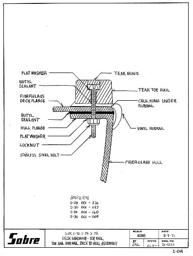
DECK HARDWARE - TOE RAIL
TOE RAIL, RUB RAIL, DECK TO HULL ASSEMBLY
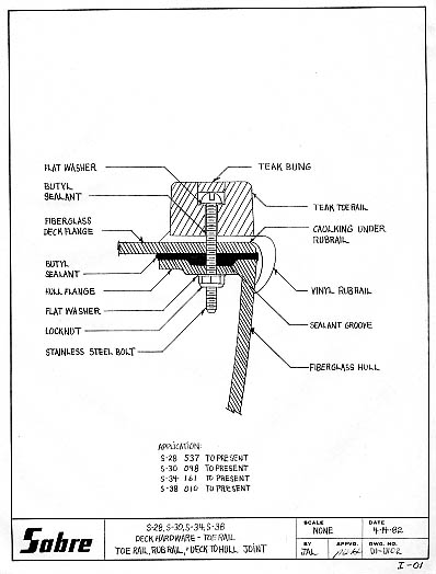
DECK HARDWARE - RIGGING
MAST STEP ASSEMBLY
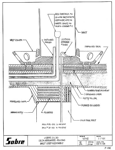
STEERING - TILLER
RUDDER AND TILLER ASSEMBLY
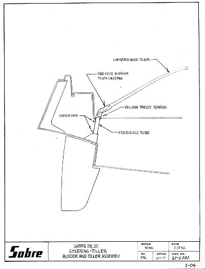
STEERING - WHEEL
RUDDER AND WHEEL ASSEMBLY
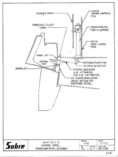
DECK HARDWARE - SAFETY
STANCHION POST ASSEMBLY
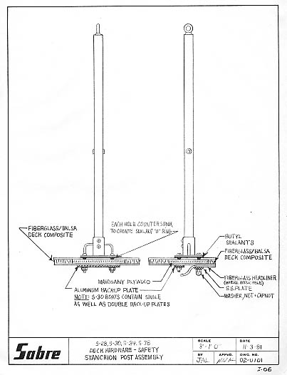
PLUMBING - THRU HULLS
COCKPIT DRAIN ASSEMBLY
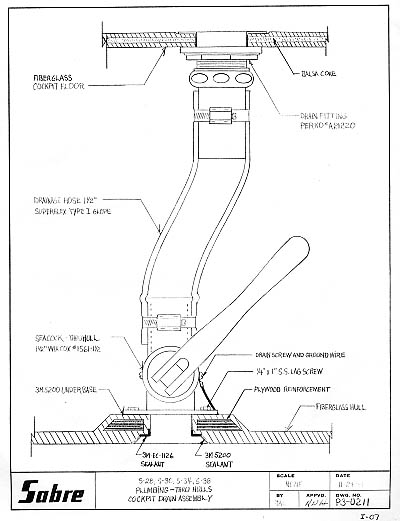
DECK HARDWARE - RIGGING
GENOA TRACK INSTALLATION
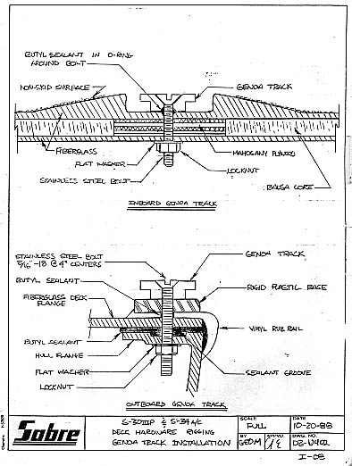
DECK HARDWARE - RIGGING
GENOA TRACK ASSEMBLY
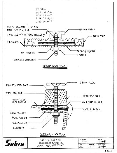
DECK HARDWARE - RIGGING
GENOA TRACK INSTALLATION
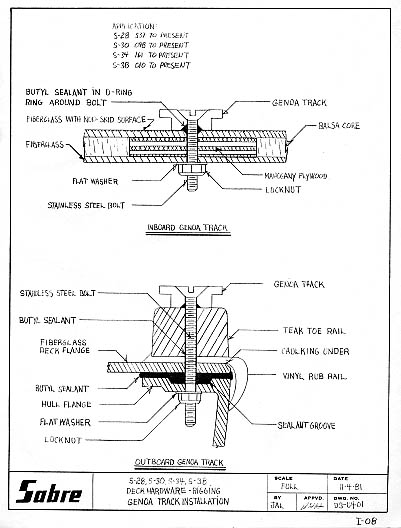
DECK HARDWARE - RIGGING
CHAINPLATE ASSEMBLY
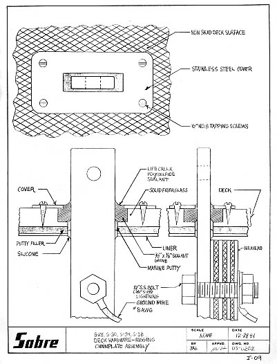
PLUMBING - THRU HULLS
THRU HULL AND SEACOCK INSTALLATION
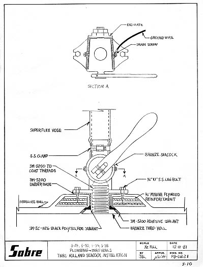
AUXILIARY POWER - SHAFT COUPLING
SHAFT LOG AND COUPLING ASSEMBLY

KEELS - GENERAL
KEEL TO HULL INSTALLATION
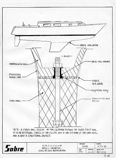
PLUMBING - THRU HULL DRAINAGE
GALLEY SINK, ICE BOX DRAINAGE SYSTEM
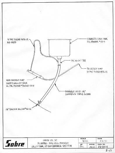
LIFTING AND STORAGE - SLINGS
SUGGESTED LIFTING STRAP LOCATIONS
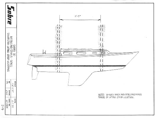
STEERING - WHEEL
RUDDER POST AND DRIVE WHEEL ASSEMBLY
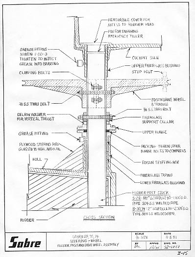
AUXILIARY POWER - PROP, SHAFT, STRUT
PROP, SHAFT, STRUT ASSEMBLY
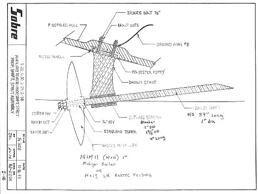
AUXILIARY POWER - FUEL SYSTEM
FUEL SYSTEM
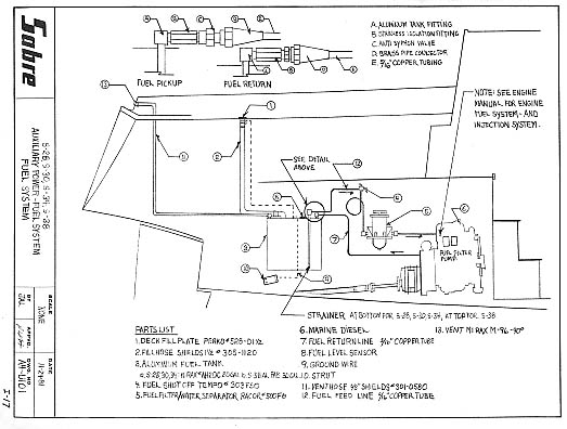
AUXILIARY POWER - COOLING + EXHAUST
ENGINE EXHAUST AND WATER INTAKE SYSTEM
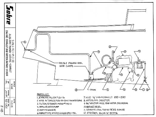
AUXILIARY POWER - COOLING + EXHAUST
HEAT TRANSFER SYSTEM

PLUMBING - WASTE WATER SYSTEM
HEAD AND HOLDING TANK
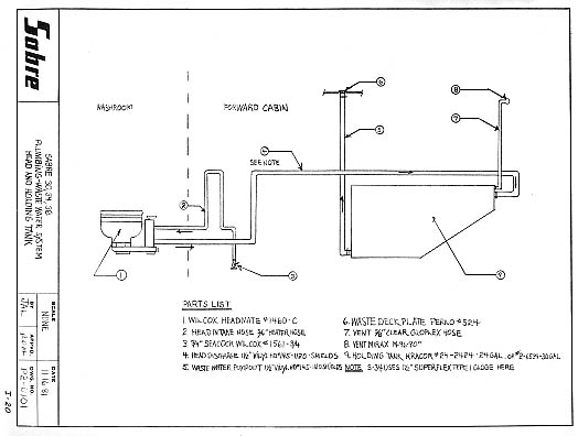
PLUMBING - WASTE WATER SYSTEM
HEAD, HOLDING TANK, "Y" VALVE AND SEACOCK

PLUMBING - WASTE WATER SYSTEM
HEAD, HOLDING TANK W/PUMPOUT, "Y" VALVE AND SEACOCK

PLUMBING - WASTE WATER SYSTEMS
LECTRA/SAN WASTE TREATMENT SYSTEM
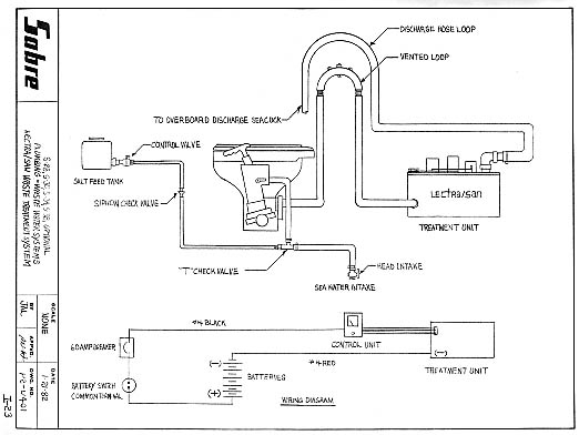
DECK HARDWARE - GENERAL
RATELCO STOVE PIPE DECK - LINER INSTALLATION
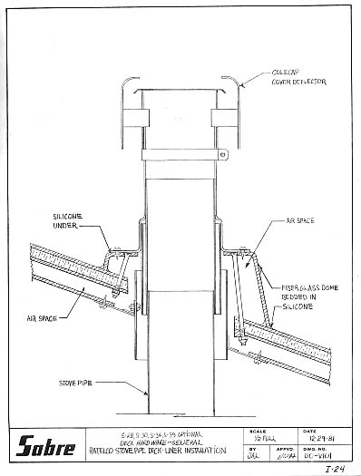
RIGGING - RUNNING RIGGING
JIFFY REEFING DETAIL
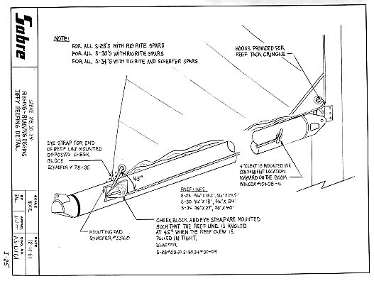
RIGGING - RUNNING RIGGING
CLEW OUTHAUL DETAIL
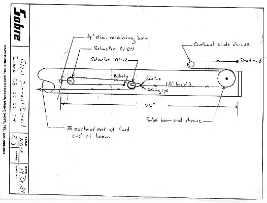
PLUMBING - WATER SYSTEMS
FRESH WATER SYSTEMS
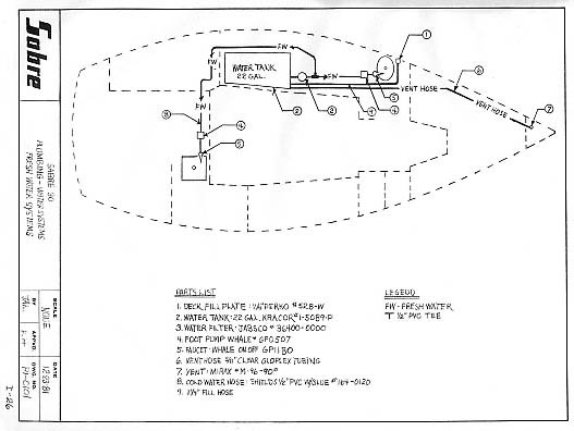
PLUMBING - WATER SYSTEMS
FRESH WATER SYSTEM WITH AUXILIARY TANK
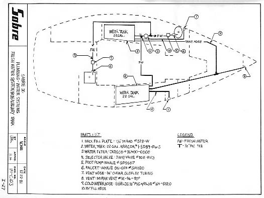
PLUMBING - WATER SYSTEMS
HOT AND COLD PRESSURIZED WATER
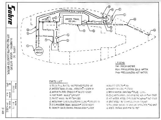
PLUMBING - WATER SYSTEMS
HOT AND COLD PRESSURIZED WATER WITH AUXILIARY TANK
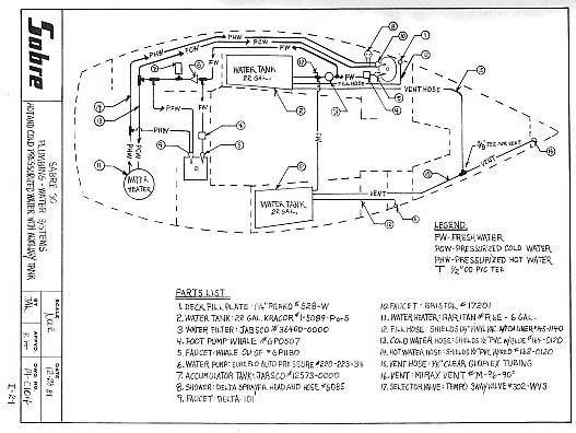
PLUMBING - WATER SYSTEMS
HOT WATER TANK DIAGRAM
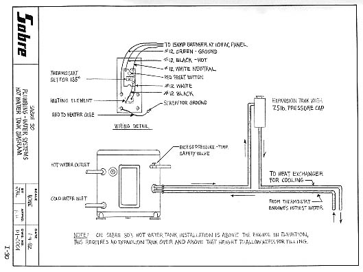
PLUMBING - BILGE DRAINAGE
BILGE DRAINAGE SYSTEMS

AUXILIARY POWER - INSTRUMENTS
INSTRUMENT LOCATION
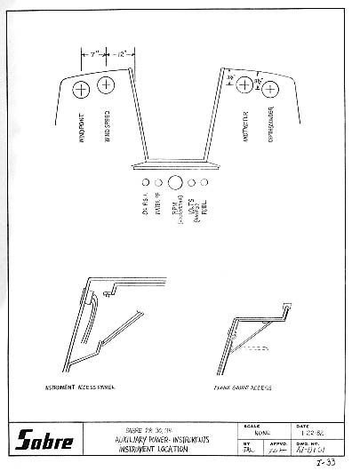
WIRING DIAGRAMS LEGEND
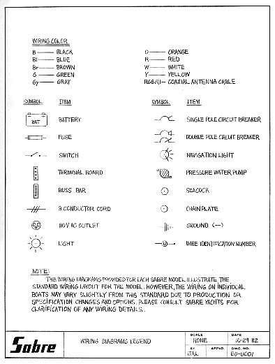
12 VOLT DC SYSTEM DIAGRAM 1
HULL 30-001 to 30-011
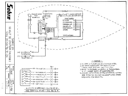
12 VOLT DC SYSTEM DIAGRAM 1
HULL 30-012 to 30-051
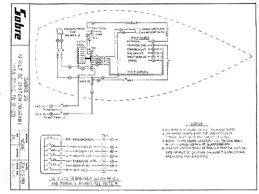
12 VOLT DC SYSTEM DIAGRAM 1
HULL 30-052 TO 30-067
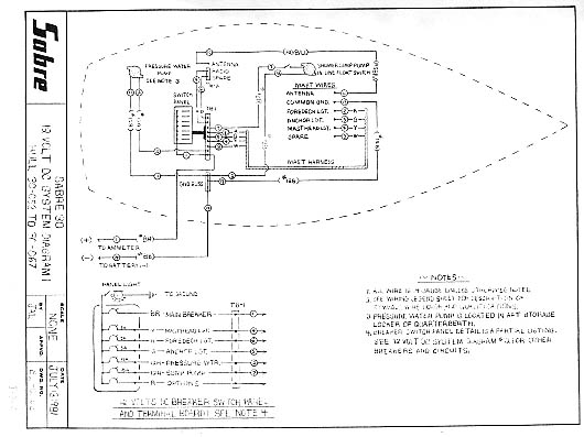
12 VOLT DC SYSTEM DIAGRAM 1
HULL 30-068 TO PRESENT
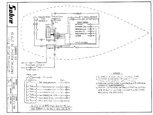
12 VOLT DC SYSTEM DIAGRAM 2
HULL 30-001 TO 30-011

12 VOLT DC SYSTEM DIAGRAM 2
HULL 30-012 TO 30-051
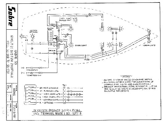
12 VOLT DC SYSTEM DIAGRAM 2
HULL 30-052 TO 30-067
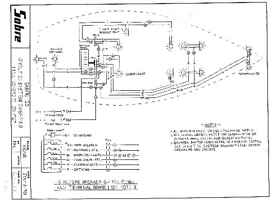
12 VOLT DC SYSTEM DIAGRAM 2
HULL 30-068 TO 30-087
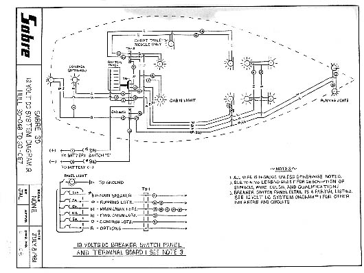
12 VOLT DC SYSTEM DIAGRAM 2
HULL 30-088 TO PRESENT
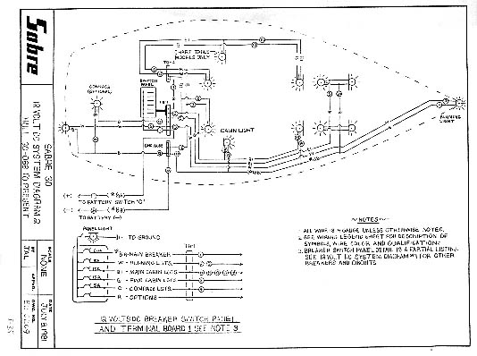
110 VOLT AC SYSTEM
HULL 30-001 TO PRESENT
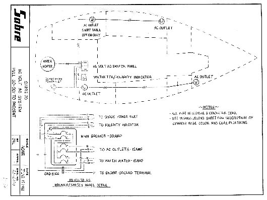
LIGHTNING PROTECTION AND BONDING SYSTEM
HULL 30-001 TO PRESENT

VOLVO MD7A ENGINE WIRING
HULL 30-001 TO 30-013
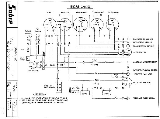
VOLVO MD7A ENGINE WIRING
HULL 30-014 TO 30-023

VOLVO MD7A ENGINE WIRING
HULL 30-024 TO 30-051
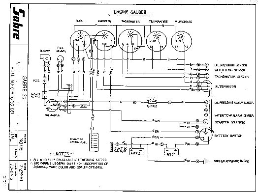
VOLVO MD7A ENGINE WIRING
HULL 30-052 TO 30-063
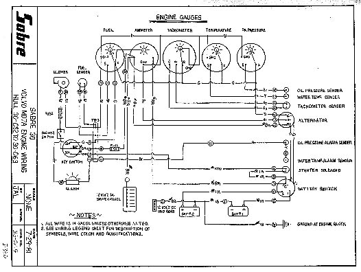
VOLVO MD7A ENGINE WIRING
HULL 30-064 TO 30-065 + 067
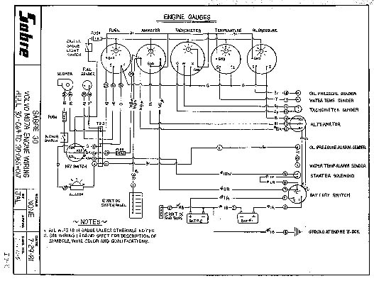
VOLVO MD7A ENGINE WIRING
HULL 30-066, 068 TO PRESENT
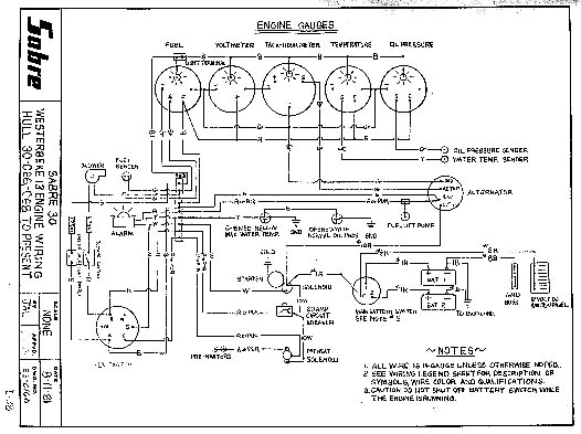
LIFTING AND STORAGE - CRADLES
FIN KEEL CRADLE - PLAN AND PROFILE
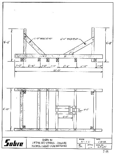
LIFTING AND STORAGE - CRADLES
FIN KEEL CRADLE - END VIEW
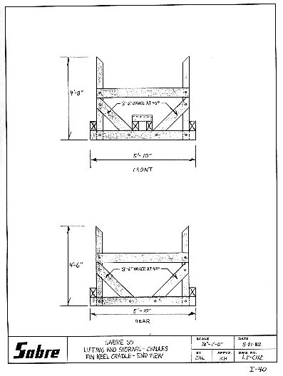
LIFTING AND STORAGE - CRADLES
SHOAL DRAFT CRADLE - PLAN AND PROFILE
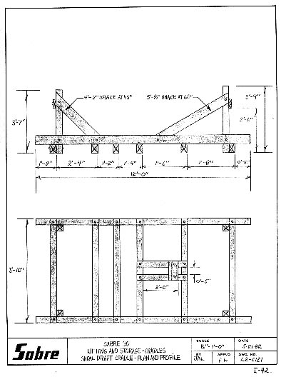
LIFTING AND STORAGE - CRADLES
SHOAL DRAFT CRADLE - END VIEW
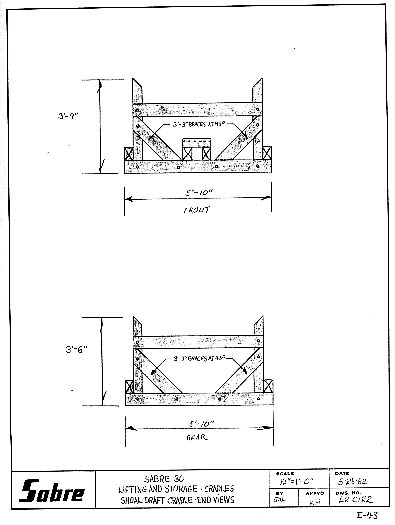
OWNER'S MANUAL INDEX